
7 Voltage Clamp
Casey Henley
The voltage clamp technique revolutionized neuroscience by allowing researchers to control and measure membrane potential, providing critical insights into voltage-gated ion channels and their roles in the action potential.
In the previous chapter, we covered ion flow and membrane potential changes that occur during the action potential in the neuron. We have this level of understanding about how ions move during the action potential because of a special technique called a voltage clamp experiment that was used in the 1950s. The voltage clamp method allows researchers to study voltage-gated ion channels by controlling the membrane potential of a neuron.
The Voltage Clamp Experiment
Initial Set-Up
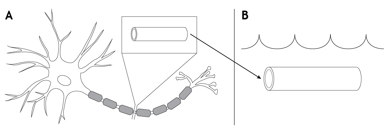
To conduct a voltage clamp experiment, a portion of the axon, which would include the cell membrane and all the voltage-gated ion channels located there, is removed from a neuron and placed into a solution that mimics that of physiological extracellular solution. The ion concentrations across the membrane, as well as the electrochemical gradients, would remain the same.
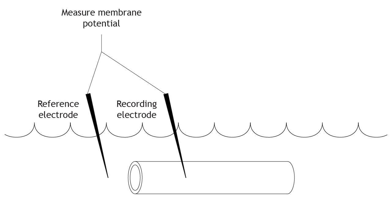
Measuring the Membrane Potential
The initial step in the voltage clamp method is to measure the membrane potential of the axon. A recording electrode is placed into the axon, and a reference electrode is placed into the extracellular solution. The voltage difference between these two electrodes is the membrane potential of the axon.
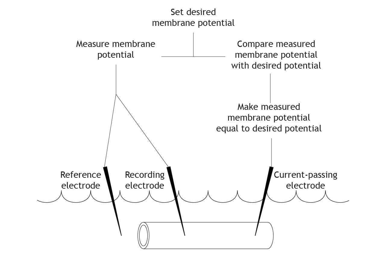
Clamping the Voltage
The researchers running the experiment can set a desired membrane potential for the cell. The equipment then compares the desired membrane potential with the measured membrane potential from the electrodes. If these values differ, current is injected into the cell to change the measured membrane potential and make it equal to the desired potential.
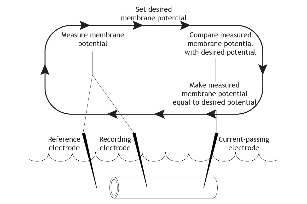
Repeat
The equipment continues this cycle for the length of the experiment. It constantly measures and compares the actual membrane potential with the desired potential, and then uses current to correct any changes, “clamping” the potential at one value.
Voltage Clamp Experiment Example
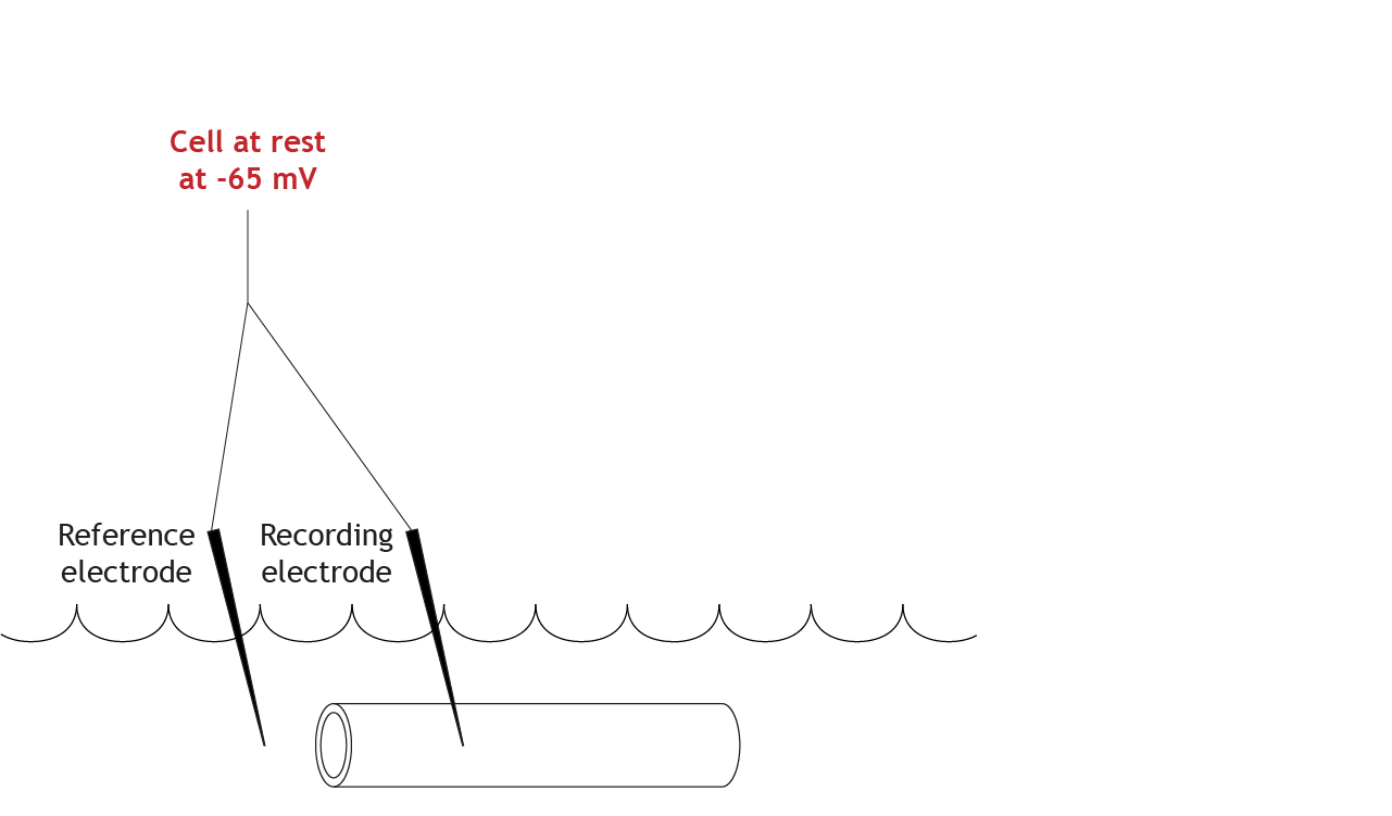
At Rest
Let’s work through the system with an example. Here is an axon bathed in the extracellular solution. The resting membrane potential is measured at -65 mV.
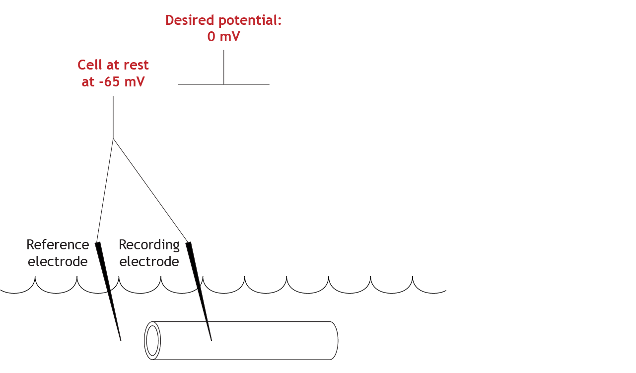
Set Clamped Membrane Potential Value
For this experiment, the desired membrane potential value is 0 mV.
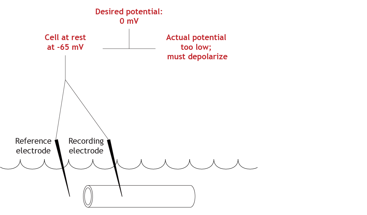
Compare Actual and Set Membrane Potential Values
The equipment will determine that the actual membrane potential of the cell is not correct (-65 mV compared to 0 mV), so the cell must depolarize to reach the set value.
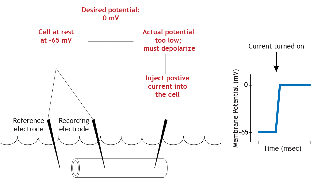
Adjust Membrane Potential
To make the axon move from its resting membrane potential to 0 mV, the current electrode will pass positive current into the cell, depolarizing the cell until the membrane potential reaches the set value.
Ion Channels Continue to Function During Voltage Clamp
The important aspect of the depolarization seen in the example is that it is above threshold. Moving the membrane potential above threshold will activate the voltage-gated ion channels. Sodium channels will open immediately, and sodium will begin rushing into the cell. This influx of positive ions would normally cause change the membrane potential to depolarize, but the voltage clamp equipment will measure the ion flow and inject a current of equal strength and opposite charge into the axon to maintain the membrane potential at 0 mV. This happens almost instantly and is a constant process, so as the ion flow changes, so does the injected current.
Animation 7.1. When the cell is clamped at 0 mV, voltage-gated sodium channels open and sodium flows into the axon. Normally this would depolarize the membrane, but the clamp equipment injects equal and opposite current to cancel the sodium influx. As a result, the membrane potential stays fixed at 0 mV despite ion flow. ‘Voltage Clamp Sodium Flow’ by Casey L. Henley (CC-BY-NC-SA). View static image of animation. View detailed alternative text.
Since the ion channels function as expected during the voltage clamp experiment, the voltage-gated sodium channels will inactivate, and the delayed voltage-gated potassium channels will open because, like the sodium channels, they are also activated when the membrane potential reaches threshold. This causes the ion flow to change from inward to outward. Normally, potassium efllux would cause a repolarization of the membrane potential, but the voltage clamp equipment will again inject a current that is equal in strength and opposite in charge to the potassium flow to keep the membrane potential steady at 0 mV.
Animation 7.2. After sodium channels inactivate, voltage-gated potassium channels open and potassium exits the axon. The clamp system injects equal and opposite current to balance the potassium efflux, keeping the membrane potential steady at 0 mV. ‘Voltage Clamp Potassium Flow’ by Casey L. Henley (CC-BY-NC-SA). View static image of animation. View detailed alternative text.
Data Collection
Researchers can determine how much current is moving through the voltage-gated ion channels by observing how much current the equipment must inject into the cell to keep the membrane potential steady. If the equipment has to inject negative current in for 2 milliseconds, then the researchers know that positive ions were flowing in for 2 milliseconds. So the voltage-clamp set up allowed researchers in the 1950s to learn about how the voltage-gated ion channels were functioning during an action potential.
Conclusion
Voltage clamp experiments have provided foundational knowledge about the function of ion channels during an action potential, helping to unravel the mechanisms of neuronal signaling.
Key Takeaways
- The voltage clamp technique measures and maintains a constant membrane potential while observing ion flow.
- Voltage-gated ion channels activate when the membrane potential reaches a threshold, causing specific ion flows.
- The equipment compensates for ion flows by injecting currents equal in strength and opposite in charge to keep the potential steady.
- Observing injected currents reveals the timing and nature of ion flow through voltage-gated channels.
Test Yourself!
Try the quiz more than once to get different questions!
