
Statics and Torque
61 The Second Condition for Equilibrium
Learning Objectives
- State the second condition that is necessary to achieve equilibrium.
- Explain torque and the factors on which it depends.
- Describe the role of torque in rotational mechanics.
Torque and the Second Condition for Equilibrium
In biological systems, just like in bridges or doorways, forces can cause rotation in addition to linear motion. To maintain balance in joints or ensure the stability of structures, it’s not enough for forces to simply cancel each other out—they also must not cause any rotational acceleration. This introduces the second condition for equilibrium: the net external torque acting on a system must be zero.
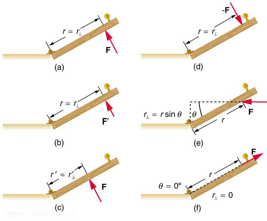
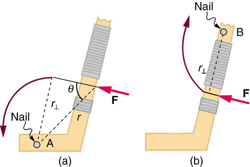
Let’s start with a relatable example—opening a door like in Figure 61.1 and Figure 61.2. You intuitively know that pushing harder opens it faster, pushing near the hinges is less effective, and pushing at an angle doesn’t help as much as pushing perpendicularly. These factors—force, point of application, and angle—are all central to torque.
The magnitude of torque [latex]\tau[/latex] is calculated using:
Here:
- [latex]r[/latex] is the distance from the pivot point to the point where the force is applied,
- [latex]F[/latex] is the magnitude of the force,
- [latex]\theta[/latex] is the angle between the direction of the force and the lever arm.
An alternative expression involves the perpendicular lever arm [latex]r_{\perp}[/latex], the shortest distance from the pivot to the line of action of the force:
Both equations give the same result—choose whichever is more convenient for the situation at hand.
The direction of torque matters. Torque can be clockwise (CW) or counterclockwise (CCW). A common sign convention is to assign positive signs to CCW torques and negative signs to CW torques.
In biomechanics, torque explains how muscles produce joint rotation, how bones resist bending, and why levers (like arms or legs) work more effectively when forces are applied farther from the pivot (joint). In engineering, torque determines the stability of beams, braces, and even seesaws.
This means the total torque acting on an object must be zero—no net rotational acceleration occurs. The pivot point used in calculations can be anywhere (including off the object), as long as it’s the same for all torques being summed. If the second condition is satisfied for one point, it’s true for any other point as well (in inertial frames).
The unit of torque is newton-meters (N·m). For example, a 40-N perpendicular force applied 0.800 m from a hinge produces a torque of:
If the force is halved, the torque is halved as well. Torque changes linearly with force and distance.
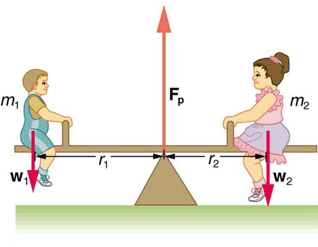
When two children balance a seesaw as shown in Figure 61.3, they satisfy the two conditions for equilibrium. Most people have perfect intuition about seesaws, knowing that the lighter child must sit farther from the pivot and that a heavier child can keep a lighter one off the ground indefinitely.
Example 61.1: She Saw Torques On A Seesaw
The two children shown in Figure 61.3 are balanced on a seesaw of negligible mass. (This assumption is made to keep the example simple—more involved examples will follow.) The first child has a mass of 26.0 kg and sits 1.60 m from the pivot.(a) If the second child has a mass of 32.0 kg, how far is she from the pivot? (b) What is [latex]{F}_{\text{p}}[/latex], the supporting force exerted by the pivot?
Strategy
Both conditions for equilibrium must be satisfied. In part (a), we are asked for a distance; thus, the second condition (regarding torques) must be used, since the first (regarding only forces) has no distances in it. To apply the second condition for equilibrium, we first identify the system of interest to be the seesaw plus the two children. We take the supporting pivot to be the point about which the torques are calculated. We then identify all external forces acting on the system.
Solution (a)
The three external forces acting on the system are the weights of the two children and the supporting force of the pivot. Let us examine the torque produced by each. Torque is defined to be
Here [latex]\theta =90º[/latex], so that
[latex]\text{sin}\phantom{\rule{0.25em}{0ex}}\theta =1[/latex] for all three forces. That means [latex]{r}_{\perp }=r[/latex] for all three. The torques exerted by the three forces are first,
second,
and third,
Note that a minus sign has been inserted into the second equation because this torque is clockwise and is therefore negative by convention. Since [latex]{F}_{\text{p}}[/latex] acts directly on the pivot point, the distance [latex]{r}_{\text{p}}[/latex] is zero. A force acting on the pivot cannot cause a rotation, just as pushing directly on the hinges of a door will not cause it to rotate. Now, the second condition for equilibrium is that the sum of the torques on both children is zero. Therefore
or
Weight is mass times the acceleration due to gravity. Entering [latex]{\mathit{mg}}_{}[/latex] for [latex]w[/latex], we get
Solve this for the unknown [latex]{r}_{2}[/latex]:
The quantities on the right side of the equation are known; thus, [latex]{r}_{2}[/latex] is
As expected, the heavier child must sit closer to the pivot (1.30 m versus 1.60 m) to balance the seesaw.
Solution (b)
This part asks for a force [latex]{F}_{\text{p}}[/latex]. The easiest way to find it is to use the first condition for equilibrium, which is
The forces are all vertical, so that we are dealing with a one-dimensional problem along the vertical axis; hence, the condition can be written as
where we again call the vertical axis the y-axis. Choosing upward to be the positive direction, and using plus and minus signs to indicate the directions of the forces, we see that
This equation yields what might have been guessed at the beginning:
So, the pivot supplies a supporting force equal to the total weight of the system:
Entering known values gives
Discussion
The two results make intuitive sense. The heavier child sits closer to the pivot. The pivot supports the weight of the two children. Part (b) can also be solved using the second condition for equilibrium, since both distances are known, but only if the pivot point is chosen to be somewhere other than the location of the seesaw’s actual pivot!
Reviewing Torque and the Second Condition for Equilibrium
Several aspects of the seesaw example illustrated in Figure 61.3 have broader implications for understanding equilibrium and torque in practical systems. First, selecting the pivot point as the reference for torque calculations simplified the problem. Since the upward support force [latex]{F}_{\text{p}}[/latex] is exerted directly at the pivot, its lever arm is zero, and therefore it produces no torque. This aligns with the second condition for equilibrium, which is valid for any pivot point. However, choosing the pivot carefully can significantly simplify the calculations.
Second, note that in our example, the acceleration due to gravity [latex]g[/latex] canceled out when computing torque. This allowed us to work with ratios of mass. But this cancellation does not occur in all problems. Always start by explicitly including the correct forces before making any simplifications.
Third, we treated each child’s weight as if it acted at a single point on the seesaw, even though their mass is distributed over an area. This approach is not an approximation. It is valid because the weight of each child acts through their respective center of gravity, and the distances [latex]{r}_{1}[/latex] and [latex]{r}_{2}[/latex] in the torque equation refer to these points directly.
Finally, the concept of torque is not limited to static equilibrium. It plays the same fundamental role in rotational motion as force does in linear motion. We will explore this deeper in the next chapter, which introduces rotational dynamics.
Take-Home Experiment — Balancing Torques with Pennies
Take a piece of modeling clay and press it onto a flat, stable surface. Now embed a cylindrical object, such as a pen or dowel, into the clay so that it acts as a horizontal pivot or fulcrum. Then place a ruler carefully on top so that it balances like a seesaw.
Place a single penny at a distance of 8 cm from the pivot point on one side. To balance the ruler, determine where you need to place:
- Two pennies on the other side
- Three pennies on the other side
Use the concept of torque to guide your prediction. Remember, for equilibrium:
Let the mass of one penny be [latex]m[/latex], and assume the force due to gravity is the same on all pennies, so the torque is proportional to mass times distance. For a single penny placed 8 cm from the pivot:
To balance this with two pennies:
For three pennies:
Try the experiment and compare the actual balance points to your calculated predictions. You are exploring the fundamental principle of torque: larger forces (more mass) must be applied at smaller distances to achieve equilibrium.
Section Summary
- The second condition for equilibrium ensures that all torques are balanced. Torque is the rotational equivalent of force, and is defined as:
[latex]\tau = rF \sin \theta[/latex]
where [latex]\tau[/latex] is torque, [latex]r[/latex] is the distance from the pivot to the point of force application, [latex]F[/latex] is the magnitude of the force, and [latex]\theta[/latex] is the angle between the force and the position vector from pivot to point of application.
- The perpendicular lever arm [latex]r_{\perp}[/latex] is the shortest distance from the pivot to the line of action of the force:
[latex]r_{\perp} = r \sin \theta[/latex]
Therefore, torque can also be calculated as:
[latex]\tau = r_{\perp} F[/latex] - The SI unit of torque is the newton-meter ([latex]\text{N} \cdot \text{m}[/latex]).
- The second condition for equilibrium requires that the net external torque on a system must be zero:
[latex]\text{net} \, \tau = 0[/latex]
By convention, counterclockwise torques are considered positive, and clockwise torques are negative.
Conceptual Questions
- What three factors affect the torque created by a force relative to a specific pivot point?
- A wrecking ball is being used to knock down a building. One tall unsupported concrete wall remains standing. If the wrecking ball hits the wall near the top, is the wall more likely to fall over by rotating at its base or by falling straight down? Explain your answer. How is it most likely to fall if it is struck with the same force at its base? Note that this depends on how firmly the wall is attached at its base.
- Mechanics sometimes put a length of pipe over the handle of a wrench when trying to remove a very tight bolt. How does this help? (It is also hazardous since it can break the bolt.)
Problems & Exercises
- (a) When opening a door, you push on it perpendicularly with a force of 55.0 N at a distance of 0.850m from the hinges. What torque are you exerting relative to the hinges? (b) Does it matter if you push at the same height as the hinges?
- When tightening a bolt, you push perpendicularly on a wrench with a force of 165 N at a distance of 0.140 m from the center of the bolt. (a) How much torque are you exerting in newton × meters (relative to the center of the bolt)? (b) Convert this torque to footpounds.
- Two children push on opposite sides of a door during play. Both push horizontally and perpendicular to the door. One child pushes with a force of 17.5 N at a distance of 0.600 m from the hinges, and the second child pushes at a distance of 0.450 m. What force must the second child exert to keep the door from moving? Assume friction is negligible.
- Use the second condition for equilibrium [latex]\text{(net τ = 0)}[/latex] to calculate [latex]{F}_{\text{p}}[/latex] in Example 61.1, employing any data given or solved for in part (a) of the example.
- Repeat the seesaw problem in Example 61.1 with the center of mass of the seesaw 0.160 m to the left of the pivot (on the side of the lighter child) and assuming a mass of 12.0 kg for the seesaw. The other data given in the example remain unchanged. Explicitly show how you follow the steps in the Problem-Solving Strategy for static equilibrium.
Glossary
- torque
- turning or twisting effectiveness of a force
- perpendicular lever arm
- the shortest distance from the pivot point to the line along which [latex]\mathbf{\text{F}}[/latex] lies
- SI units of torque
- newton times meters, usually written as N·m
- center of gravity
- the point where the total weight of the body is assumed to be concentrated
the point where the total weight of the body is assumed to be concentrated
turning or twisting effectiveness of a force
the shortest distance from the pivot point to the line along which [latex]\mathbf{\text{F}}[/latex] lies
newton times meters, usually written as N·m
