
Statics and Torque
64 Simple Machines
Learning Objectives
- Describe different simple machines.
- Calculate the mechanical advantage.
Simple machines are devices that allow us to multiply or redirect an input force—typically at the cost of increasing the distance over which the force is applied. The term “machine” comes from the Greek word meaning “to help make things easier.” Examples of simple machines include levers, pulleys, gears, wedges, and screws. These machines do not create energy but can make tasks easier by reducing the force needed. Energy is conserved: no simple machine can do more work than the energy put into it.
The ratio of the output force to the input force is called the mechanical advantage (MA):
One of the most basic simple machines is the lever, a rigid bar that pivots around a fixed point known as the fulcrum. Levers rely on torque to function, and the distances from the pivot determine how the input and output forces relate to one another.
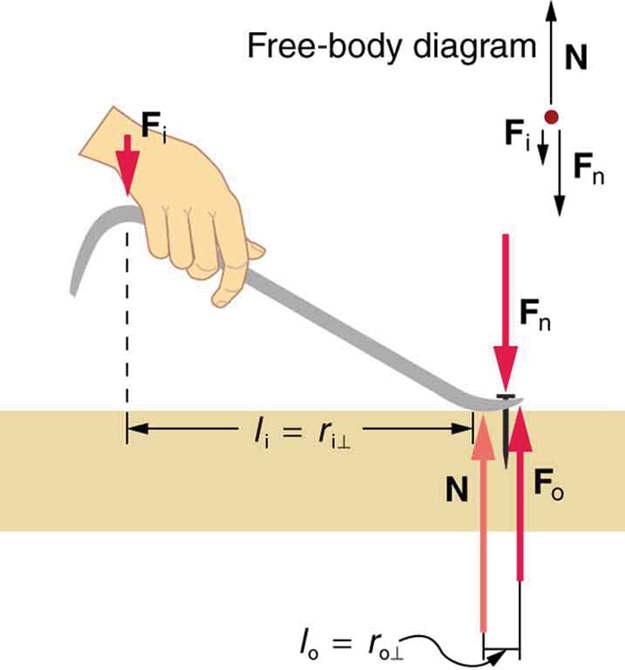
As shown in Figure 64.1, a nail puller acts as a type of lever. In this configuration, the force you apply downward with your hand is the input force [latex]F_i[/latex], and the upward force exerted on the nail is the output force [latex]F_o[/latex]. The normal force [latex]N[/latex] acts at the pivot point and does not contribute torque. In equilibrium, the torques about the pivot must cancel:
Rearranging the equation gives:
So, the mechanical advantage for a lever can also be expressed as the ratio of the input lever arm to the output lever arm:
This equation is true for all ideal levers. In the case of the nail puller, [latex]l_i[/latex] is much greater than [latex]l_o[/latex], so the mechanical advantage is greater than one—meaning a small input force yields a large output force. The longer the handle, the more advantage you gain.
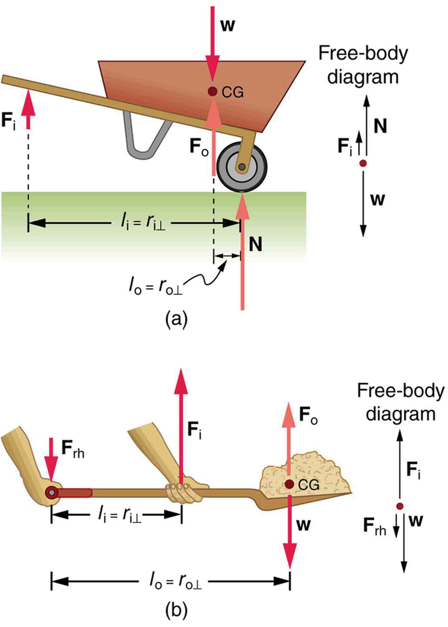
Other common examples of levers include wheelbarrows and shovels, as shown in Figure 64.2. In the case of the wheelbarrow, the output force (the load) is between the pivot (the wheel) and the input force (your hands). This is a classic second-class lever, where [latex]\text{MA} > 1[/latex].
The shovel, on the other hand, functions as a third-class lever. Here, the input force is applied between the pivot (your hand at the far end) and the output force (the load of dirt). In this setup, [latex]\text{MA} 1[/latex], meaning more input force is needed to lift the load—but it allows greater control and speed of motion.
All these machines demonstrate that mechanical advantage depends on the placement of input and output forces relative to the pivot. Whether the goal is to amplify force or increase speed, understanding levers helps us design tools that make work easier or more efficient.
Example 64.1: What is the Advantage for the Wheelbarrow?
In the wheelbarrow of Figure 64.2, the load has a perpendicular lever arm of 7.50 cm, while the hands have a perpendicular lever arm of 1.02 m. (a) What upward force must you exert to support the wheelbarrow and its load if their combined mass is 45.0 kg? (b) What force does the wheelbarrow exert on the ground?
Strategy
Here, we use the concept of mechanical advantage.
Solution
(a) In this case, [latex]\frac{{F}_{\text{o}}}{{F}_{\text{i}}}=\frac{{l}_{i}}{{l}_{o}}[/latex] becomes
Adding values into this equation yields
The free-body diagram (see Figure 64.2) gives the following normal force: [latex]{F}_{i}+N=W[/latex]. Therefore,
[latex]N=\left(\text{45.0 kg}\right)\left(9.80\phantom{\rule{0.25em}{0ex}}{\text{m/s}}^{2}\right)-\text{32.4 N}=\text{409 N}[/latex]. [latex]N[/latex] is the normal force acting on the wheel; by Newton’s third law, the force the wheel exerts on the ground is [latex]\text{409 N}[/latex].
Discussion
An even longer handle would reduce the force needed to lift the load. The MA here is [latex]\text{MA}=1\text{.}\text{02}/0\text{.}\text{0750}=\text{13}\text{.}6[/latex].
Another very common and ancient simple machine is the inclined plane. Pushing an object up a ramp requires less input force than lifting the same object straight upward—though over a longer distance. This tradeoff between force and distance is fundamental to all simple machines. Despite the reduced input force, the total work done (neglecting friction) remains the same. It is believed that the Egyptians used inclined planes to raise massive stone blocks during the construction of the pyramids.
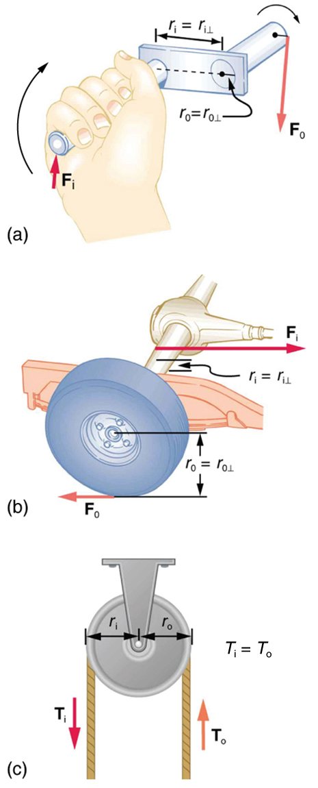
Another example of a simple machine is a crank, which is essentially a lever that can rotate fully around a pivot. This is shown in Figure 64.3(a). The physics of a crank is identical to that of a standard lever—the torque generated depends on the radius at which the force is applied. The mechanical advantage (MA) of a crank is the ratio of the output and input radii:
Many gears and wheels follow the same principle. For example, consider the simplified car axle and wheel shown in Figure 64.3(b). If the axle radius is 2.0 cm and the wheel radius is 24.0 cm, then the mechanical advantage is:
This means that the axle must exert a force of 12,000 N on the wheel to deliver a 1,000 N output force on the ground. The tradeoff is a gain in rotational speed and distance at the cost of force.
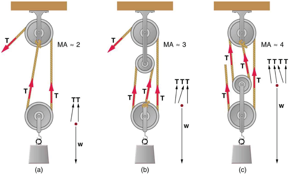
Figure 64.3(c) shows an ordinary pulley, which also acts as a simple machine. A single frictionless pulley does not multiply force—it only changes the direction of the force. Thus, it has a mechanical advantage of 1. However, combining multiple pulleys can significantly increase MA, as shown in Figure 64.4.
In a pulley system, each rope segment that supports a load contributes an equal tension force [latex]T[/latex]. Therefore, the number of rope segments effectively pulling on the load determines the total output force. For frictionless pulleys, the mechanical advantage is approximately equal to the number of these segments. For example, in Figure 64.4(a), two cables lift the load, yielding an MA ≈ 2. In panel (b), three cables support the load, giving an MA ≈ 3. In panel (c), four cables are used, giving an MA ≈ 4.
Section Summary
- Simple machines are devices that multiply or redirect force, often reducing the required input force by increasing the distance through which the force must be applied.
- The mechanical advantage (MA) is the ratio of output force to input force:
[latex]\text{MA} = \frac{F_o}{F_i}[/latex]
- Common simple machines include levers, inclined planes, pulleys, cranks, wheelbarrows, and gears.
- Combinations of pulleys or extended lever arms can significantly increase MA, enabling users to lift heavier loads with less effort.
Conceptual Questions
- Scissors are like a double-lever system. Which of the simple machines in Figure 64.1 and Figure 64.2 is most analogous to scissors?
- Suppose you pull a nail at a constant rate using a nail puller as shown in Figure 64.1 . Is the nail puller in equilibrium? What if you pull the nail with some acceleration – is the nail puller in equilibrium then? In which case is the force applied to the nail puller larger and why?
- Why are the forces exerted on the outside world by the limbs of our bodies usually much smaller than the forces exerted by muscles inside the body?
- Explain why the forces in our joints are several times larger than the forces we exert on the outside world with our limbs. Can these forces be even greater than muscle forces (see previous Question)?
Problems & Exercises
- What is the mechanical advantage of a nail puller—similar to the one shown in Figure 64.1 —where you exert a force [latex]\text{45 cm}[/latex] from the pivot and the nail is [latex]\text{1.8 cm}[/latex] on the other side? What minimum force must you exert to apply a force of [latex]\text{1250 N}[/latex] to the nail?
- Suppose you needed to raise a 250-kg mower a distance of 6.0 cm above the ground to change a tire. If you had a 2.0-m long lever, where would you place the fulcrum if your force was limited to 300 N?
- a) What is the mechanical advantage of a wheelbarrow, such as the one in Figure 64.2, if the center of gravity of the wheelbarrow and its load has a perpendicular lever arm of 5.50 cm, while the hands have a perpendicular lever arm of 1.02 m? (b) What upward force should you exert to support the wheelbarrow and its load if their combined mass is 55.0 kg? (c) What force does the wheel exert on the ground?
- A typical car has an axle with [latex]1\text{.}\text{10 cm}[/latex] radius driving a tire with a radius of [latex]\text{27}\text{.5 cm}[/latex]. What is its mechanical advantage assuming the very simplified model in Figure 64.3(b)?
- What force does the nail puller in Ecercise 1 above exert on the supporting surface? The nail puller has a mass of 2.10 kg.
- If you used an ideal pulley of the type shown in Figure 64.4(a) to support a car engine of mass [latex]\text{115 kg}[/latex], (a) What would be the tension in the rope? (b) What force must the ceiling supply, assuming you pull straight down on the rope? Neglect the pulley system’s mass.
- Repeat the previous exercise for the pulley shown in Figure 64.4(c), assuming you pull straight up on the rope. The pulley system’s mass is [latex]\text{7.00 kg}[/latex].
Glossary
- mechanical advantage
- the ratio of output to input forces for any simple machine
the ratio of output to input forces for any simple machine
