
Dynamics: Force and Newton’s Laws of Motion and Applications: Friction, Drag and Elasticity
28 Problem-Solving Strategies
Learning Objectives
- Understand and apply a problem-solving procedure to solve problems using Newton’s laws of motion.
Why Problem Solving Matters
Developing problem-solving skills is essential not only for success in physics but also for understanding the mechanical aspects of real-life biological systems—such as how forces act on joints, muscles, and surgical tools. Newton’s laws provide a powerful framework to analyze these situations, and having a reliable step-by-step strategy helps apply these laws systematically.
Strategy: Solving Force Problems Using Newton’s Laws
Step 1: Identify Forces and Draw the Situation
Start by identifying that the situation involves Newton’s laws—especially if forces are involved. Draw a sketch of the physical scenario. Then, overlay arrows to represent all external forces acting on the object or system of interest.
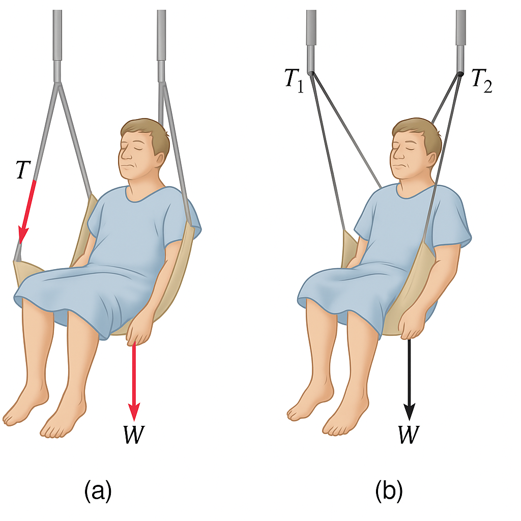
For example, consider a patient suspended in a sling supported by two straps. Just as in Figure 28.1, draw the forces acting on the system: the patient’s weight (downward), the tension in each strap (angled), and any other relevant forces like friction or support.
Tip for Biology & Health Contexts: Think of free-body diagrams as analogous to anatomical sketches showing vectors of muscle force and joint reactions.
Step 2: Define the System and List Knowns/Unknowns
Identify what you’re solving for (tension, weight, normal force, etc.), and carefully define the system of interest. This is essential because Newton’s Second Law only applies to external forces acting on that system.
Use Newton’s Third Law to distinguish internal forces (between parts of a system) from external forces (acting from outside the system).
In practice: In a biomechanics scenario, if you’re analyzing a limb, the weight of the limb is external to a muscle but internal to the entire body system.
Step 3: Draw a Free-Body Diagram (FBD)
Create a clear free-body diagram showing only the forces acting on your system. Leave out velocity or acceleration arrows—only draw forces. These diagrams are key to visual reasoning and are especially helpful when applied to biological structures like bones, tendons, and implants.
Once your FBD is complete, use Newton’s second law:
[latex]\mathbf{F}_{\text{net}} = m\mathbf{a}[/latex]
Break this into components if necessary:
-
Horizontal: [latex]{F}_{\text{net}, x} = ma_x[/latex]
-
Vertical: [latex]{F}_{\text{net}, y} = ma_y[/latex]
If the object is not accelerating in one direction, then the net force in that direction is zero.
Step 4: Solve and Evaluate
Once you have set up the correct force equations, solve algebraically for the unknowns. After solving:
-
Check for reasonableness: Does the result make sense in context?
-
Check the units: Are you solving for a force (newtons), acceleration (m/s²), or mass (kg)? If the units don’t match, there may be a mistake in setup or calculation.
-
Relate it to reality: Does the tension seem plausible for a human muscle or medical sling?
Example: Calculating the Tension in a Support Strap System
A 70-kg patient is suspended partially upright in a hospital traction system where the support strap exerts a vertical tension force through a cable connected to an IV pole hook. If the patient is stationary, what is the tension in the strap?
Solution:
Step 1: Draw a free-body diagram.
We consider the patient’s torso as the system of interest. The two external forces acting on the patient are:
-
The gravitational force (weight), [latex]\mathbf{w} = mg[/latex], acting downward.
-
The tension force [latex]\mathbf{T}[/latex], acting upward from the cable.
Step 2: Apply Newton’s Second Law.
Since the patient is stationary, there is no net acceleration:
[latex]\sum F = 0[/latex]
So,
[latex]T - w = 0 \Rightarrow T = w = mg[/latex]
Step 3: Insert known values.
[latex]T = (70.0,\text{kg})(9.80,\text{m/s}^2) = 686,\text{N}[/latex]
Answer:
The tension in the strap is [latex]686,\text{N}[/latex].
Applying Newton’s Second Law
Before writing equations for net force, it is critical to determine whether the system is accelerating—and in which direction. This reflects how Newton’s second law connects force and motion. If the system is not accelerating in a particular direction, then the net force in that direction must be zero. If it is accelerating, then:
[latex]F_{\text{net}} = ma[/latex]
This equation tells us that the total (net) force causes a mass to accelerate.
Example: Horizontal vs. Vertical Acceleration
Suppose a hospital gurney is being pushed down a hallway while supporting a patient. If the gurney accelerates horizontally but remains level (no vertical motion), the forces break down like this:
-
In the horizontal direction:
[latex]F_{\text{net},x} = ma[/latex] -
In the vertical direction:
[latex]F_{\text{net},y} = 0[/latex]
The vertical forces (like the normal force and weight) must cancel each other out, ensuring the gurney doesn’t lift off the floor or sink. Meanwhile, any horizontal acceleration results from a net applied force, such as a nurse pushing the gurney.
This method of separating directions is essential for solving realistic problems involving multiple forces in biological systems—from surgical equipment to assistive devices and physical therapy machines.
Section Summary
- To solve problems involving Newton’s laws of motion, follow the procedure described:
- Draw a sketch of the problem.
- Identify known and unknown quantities, and identify the system of interest. Draw a free-body diagram, which is a sketch showing all of the forces acting on an object. The object is represented by a dot, and the forces are represented by vectors extending in different directions from the dot. If vectors act in directions that are not horizontal or vertical, resolve the vectors into horizontal and vertical components and draw them on the free-body diagram.
- Write Newton’s second law in the horizontal and vertical directions and add the forces acting on the object. If the object does not accelerate in a particular direction (for example, the [latex]x[/latex]-direction) then [latex]{F}_{\text{net}\phantom{\rule{0.25em}{0ex}}x}=0[/latex]. If the object does accelerate in that direction, [latex]{F}_{\text{net}\phantom{\rule{0.25em}{0ex}}x}=\text{ma}[/latex].
- Check your answer. Is the answer reasonable? Are the units correct?
Problem Exercises
- A [latex]5\text{.}\text{00}×{\text{10}}^{5}\text{-kg}[/latex] rocket is accelerating straight up. Its engines produce [latex]1\text{.}\text{250}×{\text{10}}^{7}\phantom{\rule{0.25em}{0ex}}\text{N}[/latex] of thrust, and air resistance is [latex]4\text{.}\text{50}×{\text{10}}^{6}\phantom{\rule{0.25em}{0ex}}\text{N}[/latex]. What is the rocket’s acceleration? Explicitly show how you follow the steps in the Problem-Solving Strategy for Newton’s laws of motion.

Figure 28.2 - The wheels of a midsize car exert a force of 2100 N backward on the road to accelerate the car in the forward direction. If the force of friction including air resistance is 250 N and the acceleration of the car is [latex]1\text{.}{\text{80 m/s}}^{2}[/latex], what is the mass of the car plus its occupants? Explicitly show how you follow the steps in the Problem-Solving Strategy for Newton’s laws of motion. For this situation, draw a free-body diagram and write the net force equation.
- Calculate the force a 70.0-kg high jumper must exert on the ground to produce an upward acceleration 4.00 times the acceleration due to gravity. Explicitly show how you follow the steps in the Problem-Solving Strategy for Newton’s laws of motion.
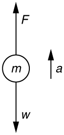
Figure 28.3 - Use Newton’s laws of motion.
- Given : [latex]a=4.00g=\left(4.00\right)\left(9.{\text{80 m/s}}^{2}\right)=\text{39.2}\phantom{\rule{0.25em}{0ex}}{\text{m/s}}^{2}\text{;}\phantom{\rule{0.25em}{0ex}}[/latex][latex]m=\text{70}\text{.}\text{0 kg}[/latex],
Find: [latex]F[/latex].
- [latex][/latex][latex][/latex][latex]\sum F\text{=+}F-w=\text{ma}\text{,}[/latex] so that [latex]F=\text{ma}+w=\text{ma}+\text{mg}=m\left(a+g\right)[/latex].
[latex]F=\left(\text{70.0 kg}\right)\left[\left(\text{39}\text{.}{\text{2 m/s}}^{2}\right)+\left(9\text{.}{\text{80 m/s}}^{2}\right)\right][/latex][latex]=3.\text{43}×{\text{10}}^{3}\text{N}[/latex]. The force exerted by the high-jumper is actually down on the ground, but [latex]F[/latex] is up from the ground and makes him jump.
- This result is reasonable, since it is quite possible for a person to exert a force of the magnitude of [latex]{\text{10}}^{3}\phantom{\rule{0.25em}{0ex}}\text{N}[/latex].
- Use Newton’s laws of motion.
- When landing after a spectacular somersault, a 40.0-kg gymnast decelerates by pushing straight down on the mat. Calculate the force she must exert if her deceleration is 7.00 times the acceleration due to gravity. Explicitly show how you follow the steps in the Problem-Solving Strategy for Newton’s laws of motion.
- A freight train consists of two [latex]8.00×{10}^{4}\text{-kg}[/latex] engines and 45 cars with average masses of [latex]5.50×{10}^{4}\phantom{\rule{0.25em}{0ex}}\text{kg}[/latex]
- What force must each engine exert backward on the track to accelerate the train at a rate of [latex]5.00×{\text{10}}^{\text{–2}}\phantom{\rule{0.25em}{0ex}}{\text{m/s}}^{2}[/latex] if the force of friction is [latex]7\text{.}\text{50}×{\text{10}}^{5}\phantom{\rule{0.25em}{0ex}}\text{N}[/latex], assuming the engines exert identical forces? This is not a large frictional force for such a massive system. Rolling friction for trains is small, and consequently trains are very energy-efficient transportation systems.
- What is the force in the coupling between the 37th and 38th cars (this is the force each exerts on the other), assuming all cars have the same mass and that friction is evenly distributed among all of the cars and engines?
- [latex]4\text{.}\text{41}×{\text{10}}^{5}\phantom{\rule{0.25em}{0ex}}\text{N}[/latex]
- [latex]1\text{.}\text{50}×{\text{10}}^{5}\phantom{\rule{0.25em}{0ex}}\text{N}[/latex]
- Commercial airplanes are sometimes pushed out of the passenger loading area by a tractor.
- An 1800-kg tractor exerts a force of [latex]1\text{.}\text{75}×{\text{10}}^{4}\phantom{\rule{0.25em}{0ex}}\text{N}[/latex] backward on the pavement, and the system experiences forces resisting motion that total 2400 N. If the acceleration is [latex]0\text{.}{\text{150 m/s}}^{2}[/latex], what is the mass of the airplane?
- Calculate the force exerted by the tractor on the airplane, assuming 2200 N of the friction is experienced by the airplane.
- Draw two sketches showing the systems of interest used to solve each part, including the free-body diagrams for each.
- A 1100-kg car pulls a boat on a trailer.
- What total force resists the motion of the car, boat, and trailer, if the car exerts a 1900-N force on the road and produces an acceleration of [latex]0\text{.}{\text{550 m/s}}^{2}[/latex]? The mass of the boat plus trailer is 700 kg.
- What is the force in the hitch between the car and the trailer if 80% of the resisting forces are experienced by the boat and trailer?
- [latex]\text{910 N}[/latex]
- [latex]1\text{.}\text{11}×{\text{10}}^{3}\phantom{\rule{0.25em}{0ex}}\text{N}[/latex]
- Answer the following questions.
- Find the magnitudes of the forces [latex]{\mathbf{\text{F}}}_{1}[/latex] and [latex]{\mathbf{\text{F}}}_{2}[/latex] that add to give the total force [latex]{\mathbf{\text{F}}}_{\text{tot}}[/latex] shown in Figure 28.4. This may be done either graphically or by using trigonometry.
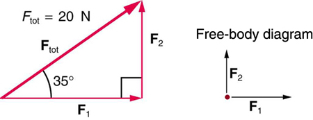
Figure 28.4 - Show graphically that the same total force is obtained independent of the order of addition of [latex]{\mathbf{\text{F}}}_{1}[/latex] and [latex]{\mathbf{\text{F}}}_{2}[/latex].
- Find the direction and magnitude of some other pair of vectors that add to give [latex]{\mathbf{\text{F}}}_{\text{tot}}[/latex]. Draw these to scale on the same drawing used in part (b) or a similar picture.
- Find the magnitudes of the forces [latex]{\mathbf{\text{F}}}_{1}[/latex] and [latex]{\mathbf{\text{F}}}_{2}[/latex] that add to give the total force [latex]{\mathbf{\text{F}}}_{\text{tot}}[/latex] shown in Figure 28.4. This may be done either graphically or by using trigonometry.
- Two children pull a third child on a snow saucer sled exerting forces [latex]{\mathbf{\text{F}}}_{1}[/latex] and [latex]{\mathbf{\text{F}}}_{2}[/latex] as shown from above in Figure 28.5. Find the acceleration of the 49.00-kg sled and child system. Note that the direction of the frictional force is unspecified; it will be in the opposite direction of the sum of [latex]{\mathbf{\text{F}}}_{1}[/latex] and [latex]{\mathbf{\text{F}}}_{2}[/latex].
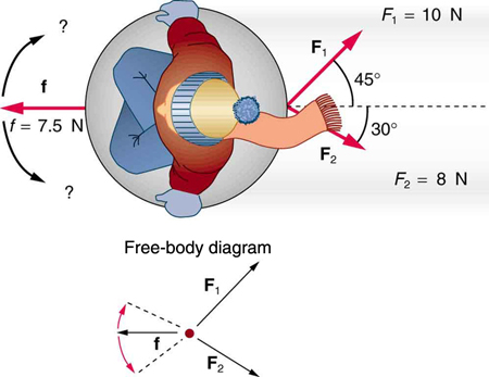
Figure 28.5: An overhead view of the horizontal forces acting on a child’s snow saucer sled. -
[latex]a=\text{0.139 m/s}[/latex],
[latex]\theta =12.4º[/latex] north of east
-
- Suppose your car was mired deeply in the mud and you wanted to use the method illustrated in Figure 28.6 to pull it out.
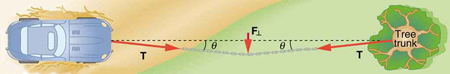
Figure 28.6 - What force would you have to exert perpendicular to the center of the rope to produce a force of 12,000 N on the car if the angle is 2.00°? In this part, explicitly show how you follow the steps in the Problem-Solving Strategy for Newton’s laws of motion.
- Real ropes stretch under such forces. What force would be exerted on the car if the angle increases to 7.00° and you still apply the force found in part (a) to its center?
- What force is exerted on the tooth in Figure 28.8 if the tension in the wire is 25.0 N? Note that the force applied to the tooth is smaller than the tension in the wire, but this is necessitated by practical considerations of how force can be applied in the mouth. Explicitly show how you follow steps in the Problem-Solving Strategy for Newton’s laws of motion.
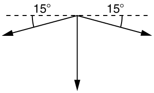
Figure 28.7 - Use Newton’s laws since we are looking for forces.
- Draw a free-body diagram:
- The tension is given as [latex]T=\text{25.0 N.}[/latex] Find [latex]{F}_{\text{app}}\text{.}[/latex] Using Newton’s laws gives:[latex]{\text{Σ F}}_{y}=0,[/latex] so that applied force is due to the y-components of the two tensions:[latex]{F}_{\text{app}}=2\phantom{\rule{0.25em}{0ex}}T\phantom{\rule{0.25em}{0ex}}\text{sin}\text{θ}=2\left(\text{25.0 N}\right)\text{sin}\left(\text{15º}\right)=\text{12.9 N}[/latex]
The x-components of the tension cancel. [latex]\sum {F}_{x}=0[/latex].
- This seems reasonable, since the applied tensions should be greater than the force applied to the tooth.
- Figure 28.9 shows Superhero and Trusty Sidekick hanging motionless from a rope. Superhero’s mass is 90.0 kg, while Trusty Sidekick’s is 55.0 kg, and the mass of the rope is negligible.
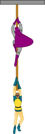
Figure 28.9: Superhero and Trusty Sidekick hang motionless on a rope as they try to figure out what to do next. Will the tension be the same everywhere in the rope? - Draw a free-body diagram of the situation showing all forces acting on Superhero, Trusty Sidekick, and the rope.
- Find the tension in the rope above Superhero.
- Find the tension in the rope between Superhero and Trusty Sidekick. Indicate on your free-body diagram the system of interest used to solve each part.
- A nurse pushes a cart by exerting a force on the handle at a downward angle [latex]\text{35.0º}[/latex] below the horizontal. The loaded cart has a mass of 28.0 kg, and the force of friction is 60.0 N. (a) Draw a free-body diagram for the system of interest. (b) What force must the nurse exert to move at a constant velocity?
- Unreasonable Results
- What is the initial acceleration of a rocket that has a mass of [latex]1\text{.}\text{50}×{\text{10}}^{6}\phantom{\rule{0.25em}{0ex}}\text{kg}[/latex] at takeoff, the engines of which produce a thrust of [latex]2\text{.}\text{00}×{\text{10}}^{6}\phantom{\rule{0.25em}{0ex}}\text{N}[/latex]? Do not neglect gravity.
- What is unreasonable about the result? (This result has been unintentionally achieved by several real rockets.)
- Which premise is unreasonable, or which premises are inconsistent? (You may find it useful to compare this problem to the rocket problem earlier in this section.)
