
Dynamics: Force and Newton’s Laws of Motion and Applications: Friction, Drag and Elasticity
27 Normal, Tension, and Other Examples of Forces
Learning Objectives
- Define normal and tension forces.
- Apply Newton’s laws of motion to solve problems involving a variety of forces.
- Use trigonometric identities to resolve weight into components.
In studying motion, it is crucial to understand the common forces that act on objects in biological systems. These include weight (gravitational force), friction, normal force, tension, and applied forces like push or pull. Each of these plays a role in the movement and stability of systems from simple machines to the human body.
Normal Force
The Normal Force
One of the most common forces in static and dynamic systems is the normal force. It arises whenever an object is in contact with a surface. The normal force acts perpendicular to the surface and counteracts other forces like gravity.
Example: Supporting a Load
Imagine holding a bag of saline solution in your hand like in Figure 27.1. Your muscles must generate an upward force to balance the weight of the bag, just as a hospital IV pole must supply a supporting force to hold the fluid bag aloft.
In physics terms, this supporting force is the normal force when the support is a surface. In a hospital setting, an exam table or patient bed must provide a sufficient normal force to support a patient’s body weight.
Key Concept:
If an object of weight [latex]\mathbf{w}[/latex] rests on a horizontal surface and remains at rest, the normal force [latex]\mathbf{N}[/latex] must balance the weight:
[latex]\mathbf{N} = \mathbf{w} = m\mathbf{g}[/latex]
Where:
- [latex]m[/latex] is the mass of the object
- [latex]g[/latex] is the acceleration due to gravity
However, if the surface is inclined, the normal force is reduced and only counters the component of the weight perpendicular to the surface:
[latex]N = mg \cos(\theta)[/latex]
Where [latex]\theta[/latex] is the angle of the incline.
![a) A person is holding a bag of saline solution in their hands. The upward force from the hands, labeled [latex]F_{\text{hand}}[/latex], is shown by an arrow pointing up. The weight of the saline bag, labeled [latex]w[/latex], is shown by an equal-length arrow pointing down. The free-body diagram below depicts a red dot with two opposing vectors: [latex]F_{\text{hand}}[/latex] pointing up and [latex]w[/latex] pointing down.(b) The bag of saline solution hangs from a hospital IV pole. A downward arrow labeled [latex]w[/latex] represents the weight of the bag, and an equal-length upward arrow labeled [latex]N[/latex] represents the normal (supporting) force exerted by the pole at the point of contact with the bag. In the corresponding free-body diagram, a red dot has two arrows: [latex]w[/latex] pointing down and [latex]N[/latex] pointing up, both starting at the same point.](https://openbooks.lib.msu.edu/app/uploads/sites/130/2025/07/saline-1.png)
Misconception Alert:
The normal force [latex]\mathbf{N}[/latex] is a vector (it has both direction and magnitude), whereas the newton (N) is a unit. Don’t confuse the two.
The Tension Force
Tension is a pulling force transmitted through a string, rope, cable, or muscle. It always pulls along the direction of the medium, and it cannot push.
Biological Example: Muscle Tension
When a muscle contracts to lift a limb, it generates tension through tendons connected to bones. Tendons act like ropes, transmitting force from muscle to skeleton.
Basic Rule:
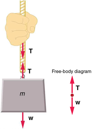
If an object hangs from a rope and remains at rest, the tension [latex]T[/latex] in the rope is equal to the object’s weight:
[latex]T = mg[/latex]
For systems involving multiple ropes or angles, the tension can be found by resolving the forces into components.
Example:
If a weight is suspended symmetrically by two angled cables each at angle [latex]\theta[/latex] from the ceiling:
[latex]2T \cos(\theta) = mg[/latex]
Solving for tension:
[latex]T = \frac{mg}{2 \cos(\theta)}[/latex]
Applications in Healthcare and Biology
- Physical therapy equipment often uses pulleys and weights; calculating tension ensures proper load application.
- Stretch receptors in muscles measure force via tension to maintain posture and avoid injury.
- Beds and tables in medical facilities must exert an appropriate normal force to safely support patients.
- Surgical sutures rely on proper tension for secure and effective closure of tissue.
Example 27.1: Weight on an Incline, a Two-Dimensional Problem
Consider the skier on a slope shown in Figure 27.2. Her mass including equipment is 60.0 kg. (a) What is her acceleration if friction is negligible? (b) What is her acceleration if friction is known to be 45.0 N?

Strategy
This is a two-dimensional problem, since the forces on the skier (the system of interest) are not parallel. The approach we have used in two-dimensional kinematics also works very well here. Choose a convenient coordinate system and project the vectors onto its axes, creating two connected one-dimensional problems to solve. The most convenient coordinate system for motion on an incline is one that has one coordinate parallel to the slope and one perpendicular to the slope. (Remember that motions along mutually perpendicular axes are independent.) We use the symbols [latex]\perp[/latex] and [latex]\parallel[/latex] to represent perpendicular and parallel, respectively. This choice of axes simplifies this type of problem, because there is no motion perpendicular to the slope and because friction is always parallel to the surface between two objects. The only external forces acting on the system are the skier’s weight, friction, and the support of the slope, respectively labeled [latex]\mathbf{\text{w}}[/latex], [latex]\mathbf{\text{f}}[/latex], and [latex]\mathbf{\text{N}}[/latex] in Figure 27.2. [latex]\mathbf{\text{N}}[/latex] is always perpendicular to the slope, and [latex]\mathbf{\text{f}}[/latex] is parallel to it. But [latex]\mathbf{\text{w}}[/latex] is not in the direction of either axis, and so the first step we take is to project it into components along the chosen axes, defining [latex]{w}_{\parallel }[/latex] to be the component of weight parallel to the slope and [latex]{w}_{\perp }[/latex] the component of weight perpendicular to the slope. Once this is done, we can consider the two separate problems of forces parallel to the slope and forces perpendicular to the slope.
Solution
The magnitude of the component of the weight parallel to the slope is [latex]{w}_{\parallel }=\mathit{w}\phantom{\rule{0.25em}{0ex}}\text{sin}\phantom{\rule{0.25em}{0ex}}\left(\text{25º}\right)=\mathit{mg}\phantom{\rule{0.25em}{0ex}}\text{sin}\phantom{\rule{0.25em}{0ex}}\left(\text{25º}\right)[/latex], and the magnitude of the component of the weight perpendicular to the slope is [latex]{w}_{\perp }=\mathit{w}\phantom{\rule{0.25em}{0ex}}\text{cos}\phantom{\rule{0.25em}{0ex}}\left(\text{25º}\right)=\mathit{mg}\phantom{\rule{0.25em}{0ex}}\text{cos}\phantom{\rule{0.25em}{0ex}}\left(\text{25º}\right)[/latex].
-
where [latex]{F}_{\text{net}\parallel }={w}_{\parallel }=\text{mg}\phantom{\rule{0.25em}{0ex}}\text{sin}\phantom{\rule{0.25em}{0ex}}\left(\text{25º}\right)[/latex], assuming no friction for this part, so that
[latex]{a}_{\parallel }=\frac{{F}_{\text{net}\parallel }}{m}=\frac{\text{mg}\phantom{\rule{0.25em}{0ex}}\text{sin}\phantom{\rule{0.25em}{0ex}}\left(\text{25º}\right)}{m}=g\phantom{\rule{0.25em}{0ex}}\text{sin}\phantom{\rule{0.25em}{0ex}}\left(\text{25º}\right)[/latex][latex]\left(9.80\phantom{\rule{0.25em}{0ex}}{\text{m/s}}^{2}\right)\left(0.4226\right)=4.14\phantom{\rule{0.25em}{0ex}}{\text{m/s}}^{2}[/latex]is the acceleration.
- Including friction. We now have a given value for friction, and we know its direction is parallel to the slope and it opposes motion between surfaces in contact. So the net external force is now
[latex]{F}_{\text{net}\parallel }={w}_{\parallel }-f,[/latex]
and substituting this into Newton’s second law, [latex]{a}_{\parallel }=\frac{{F}_{\text{net}\parallel }}{m}[/latex], gives[latex]{a}_{\parallel }=\frac{{F}_{\text{net}\mid \mid }}{m}=\frac{{w}_{\parallel }-f}{m}=\frac{\text{mg}\phantom{\rule{0.25em}{0ex}}\text{sin}\phantom{\rule{0.25em}{0ex}}\left(\text{25º}\right)-f}{m}.[/latex]We substitute known values to obtain
[latex]{a}_{\parallel }=\frac{\left(\text{60}\text{.}\text{0 kg}\right)\left(9\text{.}{\text{80 m/s}}^{2}\right)\left(0\text{.}\text{4226}\right)-\text{45}\text{.}\text{0 N}}{\text{60}\text{.}\text{0 kg}},[/latex]which yields
[latex]{a}_{\parallel }=3\text{.}{\text{39 m/s}}^{2},[/latex]which is the acceleration parallel to the incline when there is 45.0 N of opposing friction.
Neglecting friction. Since the acceleration is parallel to the slope, we need only consider forces parallel to the slope. (Forces perpendicular to the slope add to zero, since there is no acceleration in that direction.) The forces parallel to the slope are the amount of the skier’s weight parallel to the slope [latex]{w}_{\parallel }[/latex] and friction [latex]f[/latex]. Using Newton’s second law, with subscripts to denote quantities parallel to the slope,
[latex]{a}_{\parallel }=\frac{{F}_{\text{net}\parallel }}{m}[/latex]
Discussion
Since friction always opposes motion between surfaces, the acceleration is smaller when there is friction than when there is none. In fact, it is a general result that if friction on an incline is negligible, then the acceleration down the incline is [latex]a=g\phantom{\rule{0.25em}{0ex}}\text{sin}\theta[/latex], regardless of mass. This is related to the previously discussed fact that all objects fall with the same acceleration in the absence of air resistance. Similarly, all objects, regardless of mass, slide down a frictionless incline with the same acceleration (if the angle is the same).
- Including friction. We now have a given value for friction, and we know its direction is parallel to the slope and it opposes motion between surfaces in contact. So the net external force is now
Resolving Weight into Components
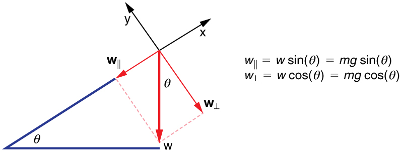
When an object rests on an incline that makes an angle [latex]\theta[/latex] with the horizontal, the force of gravity acting on the object is divided into two components: a force acting perpendicular to the plane, [latex]{\mathbf{\text{w}}}{\perp}[/latex], and a force acting parallel to the plane, [latex]{\mathbf{\text{w}}}{\parallel}[/latex].
The perpendicular force of weight, [latex]{\mathbf{\text{w}}}{\perp}[/latex], is typically equal in magnitude and opposite in direction to the normal force, [latex]\mathbf{N}[/latex]. The force acting parallel to the plane, [latex]{\mathbf{\text{w}}}{\parallel}[/latex], causes the object to accelerate down the incline. The force of friction, [latex]\mathbf{f}[/latex], opposes this motion and acts up the incline.
Using trigonometry, the components of weight are:
[latex]{w}{\parallel} = mg \sin(\theta)[/latex]
[latex]{w}{\perp} = mg \cos(\theta)[/latex]
These come from analyzing the right triangle formed by the weight vector and its components. This method reinforces understanding over memorization.
Take-Home Experiment: Force Parallel
Try suspending a small weight from a rubber band vertically and then on an inclined board. Measure the rubber band’s stretch in both orientations. Try different angles. What do you observe about the tension required to keep the object from sliding?
Tension
Tension is a pulling force transmitted through a string, rope, cable, or muscle. It always pulls along the direction of the medium, and it cannot push.
Biological Example: Muscle Tension
When a muscle contracts to lift a limb, it generates tension through tendons connected to bones. Tendons act like ropes, transmitting force from muscle to skeleton.
Basic Rule:
If an object hangs from a rope and remains at rest as shown in Figure 27.4, the tension [latex]T[/latex] in the rope is equal to the object’s weight:
[latex]T = mg[/latex]
Example:
If a 5.00-kg IV mass is hanging at rest, the tension in the supporting rope or tubing is:
[latex]T = (5.00\ \text{kg})(9.80\ \text{m/s}^2) = 49.0\ \text{N}[/latex]
In more complex setups, such as split supports at angles:
[latex]2T \cos(\theta) = mg[/latex]
Solving for tension:
[latex]T = \frac{mg}{2 \cos(\theta)}[/latex]
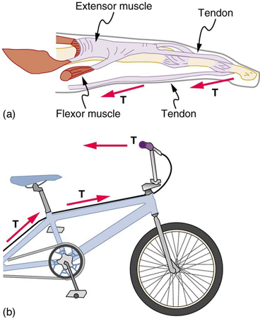
Flexible connectors are often used to transmit forces around corners, such as in a hospital traction system, a finger joint, or a bicycle brake cable. If there is no friction, the tension is transmitted undiminished. Only its direction changes, and it is always parallel to the flexible connector. This is illustrated in Figure 27.5 (a) and (b).
Example 27.2: What Is the Tension in a Tightrope?
Calculate the tension in the wire supporting the 70.0-kg tightrope walker shown in Figure 27.6.
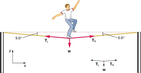
Strategy
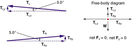
As you can see in the figure, the wire is not perfectly horizontal (it cannot be!), but is bent under the person’s weight. Thus, the tension on either side of the person has an upward component that can support his weight. As usual, forces are vectors represented pictorially by arrows having the same directions as the forces and lengths proportional to their magnitudes. The system is the tightrope walker, and the only external forces acting on him are his weight [latex]\mathbf{\text{w}}[/latex] and the two tensions [latex]{\mathbf{\text{T}}}_{\text{L}}[/latex] (left tension) and [latex]{\mathbf{\text{T}}}_{\text{R}}[/latex] (right tension), as illustrated. It is reasonable to neglect the weight of the wire itself. The net external force is zero since the system is stationary. A little trigonometry can now be used to find the tensions. One conclusion is possible at the outset—we can see from part (b) of the figure that the magnitudes of the tensions [latex]{T}_{\text{L}}[/latex] and [latex]{T}_{\text{R}}[/latex] must be equal. This is because there is no horizontal acceleration in the rope, and the only forces acting to the left and right are [latex]{T}_{\text{L}}[/latex] and [latex]{T}_{R}[/latex]. Thus, the magnitude of those forces must be equal so that they cancel each other out.
Whenever we have two-dimensional vector problems in which no two vectors are parallel, the easiest method of solution is to pick a convenient coordinate system and project the vectors onto its axes. In this case the best coordinate system has one axis horizontal and the other vertical. We call the horizontal the [latex]x[/latex]-axis and the vertical the [latex]y[/latex]-axis.
Solution
First, we need to resolve the tension vectors into their horizontal and vertical components. It helps to draw a new free-body diagram showing all of the horizontal and vertical components of each force acting on the system.
Consider the horizontal components of the forces (denoted with a subscript [latex]x[/latex]):
The net external horizontal force [latex]{F}_{\text{net}x}=0[/latex], since the person is stationary. Thus,
Now, observe Figure 27.7. You can use trigonometry to determine the magnitude of [latex]{T}_{\text{L}}[/latex] and [latex]{T}_{\text{R}}[/latex]. Notice that:
Equating [latex]{T}_{\text{L}x}[/latex] and [latex]{T}_{\text{R}x}[/latex]:
Thus,
as predicted. Now, considering the vertical components (denoted by a subscript [latex]y[/latex]), we can solve for [latex]T[/latex]. Again, since the person is stationary, Newton’s second law implies that net [latex]{F}_{y}=0[/latex]. Thus, as illustrated in the free-body diagram in Figure 27.7,
Observing Figure 27.7, we can use trigonometry to determine the relationship between
[latex]{T}_{\text{L}y}[/latex],
[latex]{T}_{\text{R}y}[/latex],
and [latex]T[/latex].
As we determined from the analysis in the horizontal direction,
[latex]{T}_{\text{L}}={T}_{\text{R}}=T[/latex]:
Now, we can substitute the values for [latex]{T}_{\text{L}y}[/latex] and [latex]{T}_{\text{R}y}[/latex], into the net force equation in the vertical direction:
and
so that
and the tension is
Discussion
Note that the vertical tension in the wire acts as a normal force that supports the weight of the tightrope walker. The tension is almost six times the 686-N weight of the tightrope walker. Since the wire is nearly horizontal, the vertical component of its tension is only a small fraction of the tension in the wire. The large horizontal components are in opposite directions and cancel, and so most of the tension in the wire is not used to support the weight of the tightrope walker.
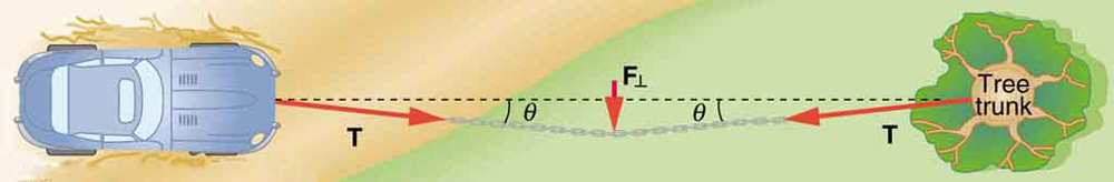
If we wish to generate a very large tension in a rope or chain, all we need to do is apply a perpendicular force to the middle of the flexible connector. This principle is illustrated in Figure 27.8., where a force [latex]{F}_{\perp}[/latex] is applied at the midpoint of a chain. The resulting tension is given by:
[latex]T = \frac{F_{\perp}}{2 \sin(\theta)}[/latex]
Here, [latex]\theta[/latex] is the angle between the chain and the horizontal. As [latex]\theta[/latex] becomes smaller (i.e., the chain becomes more horizontal), [latex]\sin(\theta)[/latex] approaches zero, making the tension [latex]T[/latex] grow very large. This explains why even light objects can create substantial tension in a tightrope or sagging cable.
This concept helps explain:
-
The force required to pull a vehicle from mud using a chain.
-
The need for slack in climbing ropes to avoid dangerously high tensions.
-
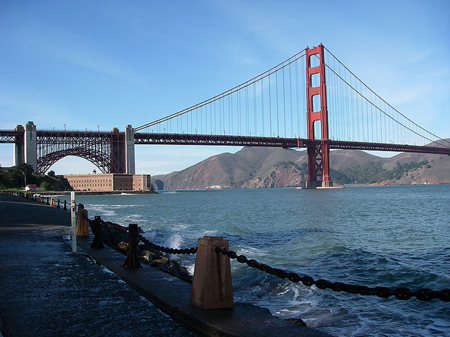
The sagging shape of suspension bridges and surgical retractors under distributed load, as seen in Figure 27.9.
Extended Topic: Real Forces and Inertial Frames
In physics—especially when applied to biological systems—it’s important to distinguish between real forces and fictitious forces.
-
Real forces have a physical origin. These include gravity, friction, tension, and normal forces—forces that can be measured and that result from interactions between objects or fields.
-
Fictitious forces arise when an observer is in a non-inertial (accelerating or rotating) frame of reference. These forces don’t come from any physical interaction; rather, they’re artifacts of observing motion from a moving or rotating perspective.
Example:
If you’re inside a rapidly decelerating ambulance and feel like you’re being “thrown forward,” that’s not a real force acting on you—it’s the result of the ambulance slowing down beneath you. In the inertial (ground) frame, your body is trying to continue moving forward at constant speed (inertia), while the vehicle is slowing down. To someone inside the ambulance, it feels like a mysterious force is pushing them forward, but this is just a fictitious force.
Satellite Example:
Similarly, a satellite moving north over Earth appears—when viewed from Earth—to veer west. That’s because Earth rotates eastward underneath the satellite. From Earth’s frame, this deflection seems like a force (called the Coriolis force), but it’s not caused by any physical interaction—only by Earth’s rotation.
Inertial Frames:
An inertial frame of reference is one in which all forces are real, and Newton’s laws of motion apply directly and accurately. Unless otherwise stated, all examples and problems in this course assume that we are working within an inertial frame.
For biological systems on Earth, this is almost always a good assumption because Earth’s rotation is relatively slow. However, in large-scale systems—like ocean currents or blood flow in the body under rotation (e.g., in a centrifuge)—fictitious forces can become relevant and must be accounted for.
PhET Explorations: Forces in 1 Dimension
Figure 27.10: Forces in 1 Dimension
Section Summary
- When objects rest on a surface, the surface applies a force to the object that supports the weight of the object. This supporting force acts perpendicular to and away from the surface. It is called a normal force, [latex]\mathbf{\text{N}}[/latex].
- When objects rest on a non-accelerating horizontal surface, the magnitude of the normal force is equal to the weight of the object:
[latex]N=\text{mg}.[/latex]
- When objects rest on an inclined plane that makes an angle [latex]\theta[/latex] with the horizontal surface, the weight of the object can be resolved into components that act perpendicular ([latex]{\mathbf{\text{w}}}_{\perp }[/latex]) and parallel ([latex]{\mathbf{\text{w}}}_{\parallel }[/latex]) to the surface of the plane. These components can be calculated using:
[latex]{w}_{\parallel }=w\phantom{\rule{0.25em}{0ex}}\text{sin}\phantom{\rule{0.25em}{0ex}}\left(\theta \right)=\text{mg}\phantom{\rule{0.25em}{0ex}}\text{sin}\phantom{\rule{0.25em}{0ex}}\left(\theta \right)[/latex][latex]{w}_{\perp }=w\phantom{\rule{0.25em}{0ex}}\text{cos}\phantom{\rule{0.25em}{0ex}}\left(\theta \right)=\text{mg}\phantom{\rule{0.25em}{0ex}}\text{cos}\phantom{\rule{0.25em}{0ex}}\left(\theta \right).[/latex]
- The pulling force that acts along a stretched flexible connector, such as a rope or cable, is called tension, [latex]\mathbf{\text{T}}[/latex]. When a rope supports the weight of an object that is at rest, the tension in the rope is equal to the weight of the object:
[latex]T=\text{mg}.[/latex]
- In any inertial frame of reference (one that is not accelerated or rotated), Newton’s laws have the simple forms given in this chapter and all forces are real forces having a physical origin.
Conceptual Questions
- If a leg is suspended by a traction setup as shown in Figure 27.11, what is the tension in the rope?
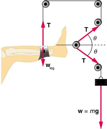
Figure 27.11: A leg is suspended by a traction system in which wires are used to transmit forces. Frictionless pulleys change the direction of the force T without changing its magnitude. - In a traction setup for a broken bone, with pulleys and rope available, how might we be able to increase the force along the tibia using the same weight? (See Figure 27.11.) (Note that the tibia is the shin bone shown in this image.)
Problem Exercises
- Two teams of nine members each engage in a tug of war. Each of the first team’s members has an average mass of 68 kg and exerts an average force of 1350 N horizontally. Each of the second team’s members has an average mass of 73 kg and exerts an average force of 1365 N horizontally.
- What is magnitude of the acceleration of the two teams?
- What is the tension in the section of rope between the teams?
(a) [latex]0.{\text{11 m/s}}^{2}[/latex]
(b)[latex]1\text{.}2×{\text{10}}^{4}\phantom{\rule{0.25em}{0ex}}\text{N}[/latex]
- What force does a trampoline have to apply to a 45.0-kg gymnast to accelerate her straight up at [latex]7\text{.}{\text{50 m/s}}^{2}[/latex]? Note that the answer is independent of the velocity of the gymnast—she can be moving either up or down, or be stationary.
- Calculate the tension in a vertical strand of spider web if a spider of mass [latex]8\text{.}\text{00}×{\text{10}}^{-5}\phantom{\rule{0.25em}{0ex}}\text{kg}[/latex] hangs motionless on it.
- Calculate the tension in a horizontal strand of spider web if the same spider sits motionless in the middle of it much like the tightrope walker in Figure 27.6. The strand sags at an angle of [latex]\text{12º}[/latex] below the horizontal. Compare this with the tension in the vertical strand (find their ratio).
(a)[latex]7\text{.}\text{84}×{\text{10}}^{-4}\phantom{\rule{0.25em}{0ex}}\text{N}[/latex]
(b)[latex]1\text{.}\text{89}×{\text{10}}^{–3}\phantom{\rule{0.25em}{0ex}}\text{N}[/latex] . This is 2.41 times the tension in the vertical strand.
- Suppose a 60.0-kg gymnast climbs a rope.
- What is the tension in the rope if he climbs at a constant speed?
- What is the tension in the rope if he accelerates upward at a rate of [latex]1\text{.}{\text{50 m/s}}^{2}[/latex]?
- Show that, as stated in the text, a force [latex]{\mathbf{\text{F}}}_{\perp }[/latex] exerted on a flexible medium at its center and perpendicular to its length (such as on the tightrope wire in Figure 27.6) gives rise to a tension of magnitude [latex]T=\frac{{F}_{\perp }}{2\phantom{\rule{0.25em}{0ex}}\text{sin}\phantom{\rule{0.25em}{0ex}}\left(\theta \right)}[/latex].
- Newton’s second law applied in vertical direction gives
[latex]{F}_{y}=F-2T\phantom{\rule{0.25em}{0ex}}\text{sin}\phantom{\rule{0.25em}{0ex}}\theta =0[/latex][latex]{F}_{}=2T\phantom{\rule{0.25em}{0ex}}\text{sin}\phantom{\rule{0.25em}{0ex}}\theta[/latex][latex]T=\frac{{F}_{}}{\text{2 sin}\phantom{\rule{0.25em}{0ex}}\theta }.[/latex]
- Newton’s second law applied in vertical direction gives
- Consider the baby being weighed in Figure 27.12.
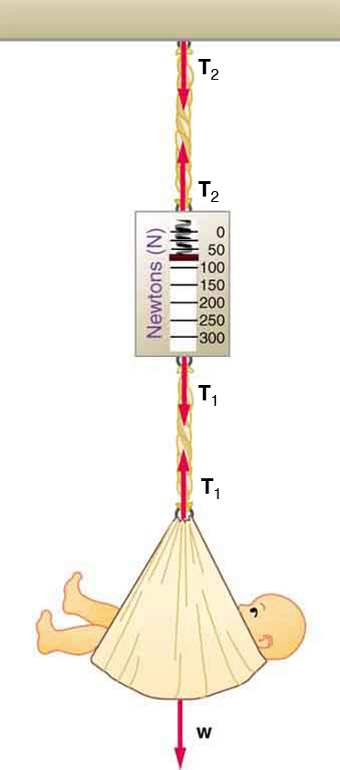
Figure 27.12: A baby is weighed using a spring scale. - What is the mass of the child and basket if a scale reading of 55 N is observed?
- What is the tension [latex]{T}_{1}[/latex] in the cord attaching the baby to the scale?
- What is the tension [latex]{T}_{2}[/latex] in the cord attaching the scale to the ceiling, if the scale has a mass of 0.500 kg?
- Draw a sketch of the situation indicating the system of interest used to solve each part. The masses of the cords are negligible.
Glossary
- inertial frame of reference
- a coordinate system that is not accelerating; all forces acting in an inertial frame of reference are real forces, as opposed to fictitious forces that are observed due to an accelerating frame of reference
- normal force
- the force that a surface applies to an object to support the weight of the object; acts perpendicular to the surface on which the object rests
- tension
- the pulling force that acts along a medium, especially a stretched flexible connector, such as a rope or cable; when a rope supports the weight of an object, the force on the object due to the rope is called a tension force
the force that a surface applies to an object to support the weight of the object; acts perpendicular to the surface on which the object rests
the pulling force that acts along a medium, especially a stretched flexible connector, such as a rope or cable; when a rope supports the weight of an object, the force on the object due to the rope is called a tension force
a coordinate system that is not accelerating; all forces acting in an inertial frame of reference are real forces, as opposed to fictitious forces that are observed due to an accelerating frame of reference
