
Rotational motion and angular momentum
68 Gyroscopic Effects: Vector Aspects of Angular Momentum
Learning Objectives
- Describe the right-hand rule to find the direction of angular velocity, momentum, and torque.
- Explain the gyroscopic effect.
- Study how Earth acts like a gigantic gyroscope.
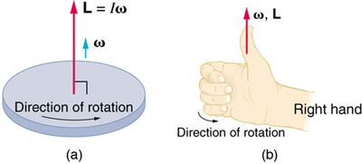
Angular momentum is a vector and, therefore, has direction as well as magnitude. Torque affects both the direction and the magnitude of angular momentum. What is the direction of the angular momentum of a rotating object like the disk in Figure 68.1? The figure shows the right-hand rule used to find the direction of both angular momentum and angular velocity. Both [latex]\mathbf{L}[/latex] and [latex]\mathbf{\omega}[/latex] are vectors—each has direction and magnitude. Both can be represented by arrows. The right-hand rule defines both to be perpendicular to the plane of rotation in the direction shown. Because angular momentum is related to angular velocity by
the direction of [latex]\mathbf{L}[/latex] is the same as the direction of [latex]\mathbf{\omega}[/latex]. Notice in the figure that both point along the axis of rotation.
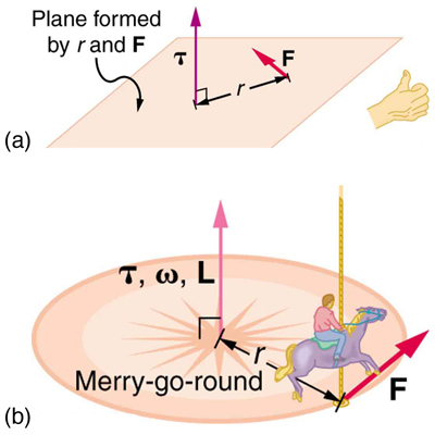
Now, recall that torque changes angular momentum as expressed by:
This equation means that the direction of [latex]\Delta \mathbf{L}[/latex] is the same as the direction of the torque [latex]\mathbf{\tau}[/latex] that creates it. This result is illustrated in Figure 68.2, which shows the direction of torque and the angular momentum it creates.
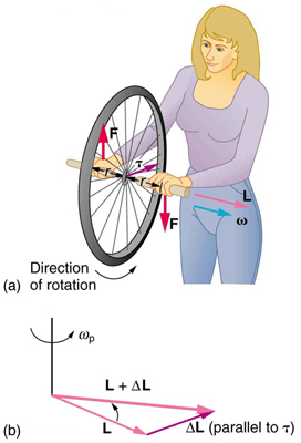
Let us now consider a bicycle wheel with a couple of handles attached to it, as shown in Figure 68.3. This device is popular in physics demos because it does unexpected things. With the wheel rotating as shown, its angular momentum is to the woman’s left. If she tries to rotate the wheel by applying forces, those forces create a torque that is horizontal toward her. This torque changes [latex]\mathbf{L}[/latex] in the same direction, perpendicular to the original [latex]\mathbf{L}[/latex], thus altering the direction of [latex]\mathbf{L}[/latex] but not its magnitude. The axis of the wheel moves perpendicular to the applied forces, not in the expected direction.
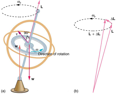
This same logic explains the behavior of gyroscopes. Figure 68.4 shows the two forces acting on a spinning gyroscope. The torque produced is perpendicular to [latex]\mathbf{L}[/latex], changing its direction but not magnitude. The gyroscope precesses around a vertical axis due to the horizontal torque. If the gyroscope is not spinning, it gains angular momentum in the direction of the torque and falls over.
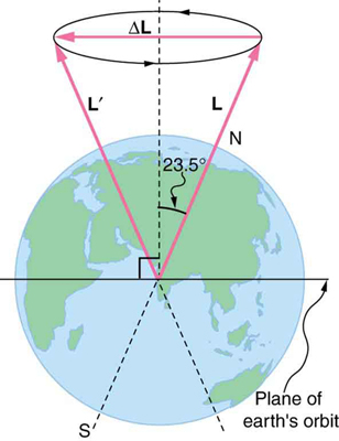
Earth acts like a gigantic gyroscope. Its angular momentum vector points along its rotation axis toward Polaris, the North Star. However, due to torque from the Sun and Moon acting on its oblate shape, Earth precesses slowly—once every ~26,000 years.
Check Your Understanding
Question: Rotational kinetic energy is associated with angular momentum. Does that mean that rotational kinetic energy is a vector?
Answer: No, energy is always a scalar, regardless of motion. Rotational kinetic energy, like linear kinetic energy, depends only on the magnitude of velocity—not its direction.
Section Summary
- Torque is perpendicular to the plane formed by [latex]r[/latex] and [latex]\mathbf{F}[/latex] and points in the direction of your right thumb when curling your fingers along [latex]\mathbf{F}[/latex]. Its direction matches that of the angular momentum it produces.
- A gyroscope precesses around a vertical axis because the applied torque is horizontal and perpendicular to [latex]\mathbf{L}[/latex]. If not spinning, the gyroscope falls over due to rotation around a horizontal axis.
- Earth acts like a gyroscope: its angular momentum points toward Polaris, but it slowly precesses due to solar and lunar torques on its non-spherical shape.
Conceptual Questions
- While driving his motorcycle at highway speed, a physics student notices that pulling back lightly on the right handlebar tips the cycle to the left and produces a left turn. Explain why this happens.
- Gyroscopes used in guidance systems to indicate directions in space must have an angular momentum that does not change in direction. Yet they are often subjected to large forces and accelerations. How can the direction of their angular momentum be constant when they are accelerated?
Problem Exercises
- Integrated Concepts The axis of Earth makes a 23.5° angle with a direction perpendicular to the plane of Earth’s orbit. As shown in Figure 68.5, this axis precesses, making one complete rotation in 25,780 y. (a) Calculate the change in angular momentum in half this time. (b) What is the average torque producing this change in angular momentum? (c) If this torque were created by a single force (it is not) acting at the most effective point on the equator, what would its magnitude be?
Glossary
- right-hand rule
- direction of angular velocity ω and angular momentum L in which the thumb of your right hand points when you curl your fingers in the direction of the disk’s rotation
direction of angular velocity ω and angular momentum L in which the thumb of your right hand points when you curl your fingers in the direction of the disk’s rotation
