
Fluid Dynamics and Its Biological and Medical Applications
86 Bernoulli’s Equation
Learning Objectives
- Explain the terms in Bernoulli’s equation.
- Explain how Bernoulli’s equation is related to conservation of energy.
- Explain how to derive Bernoulli’s principle from Bernoulli’s equation.
- Calculate with Bernoulli’s principle.
- List some applications of Bernoulli’s principle.
Bernoulli’s Principle: Fluid Motion, Pressure, and Energy Conservation
When a fluid enters a narrower region of a vessel or tube, its speed increases. As a result, its kinetic energy also increases. But where does this added kinetic energy come from? The answer lies in the work-energy principle: the energy comes from the net work done on the fluid, either by an external pressure difference or by gravity if the fluid’s vertical position changes.
This equation, the work-energy theorem, tells us that a net force (and thus net work) changes the kinetic energy of the fluid. When the channel narrows, pressure differences arise: since pressure multiplied by area equals force, this pressure difference leads to a force that accelerates the fluid.
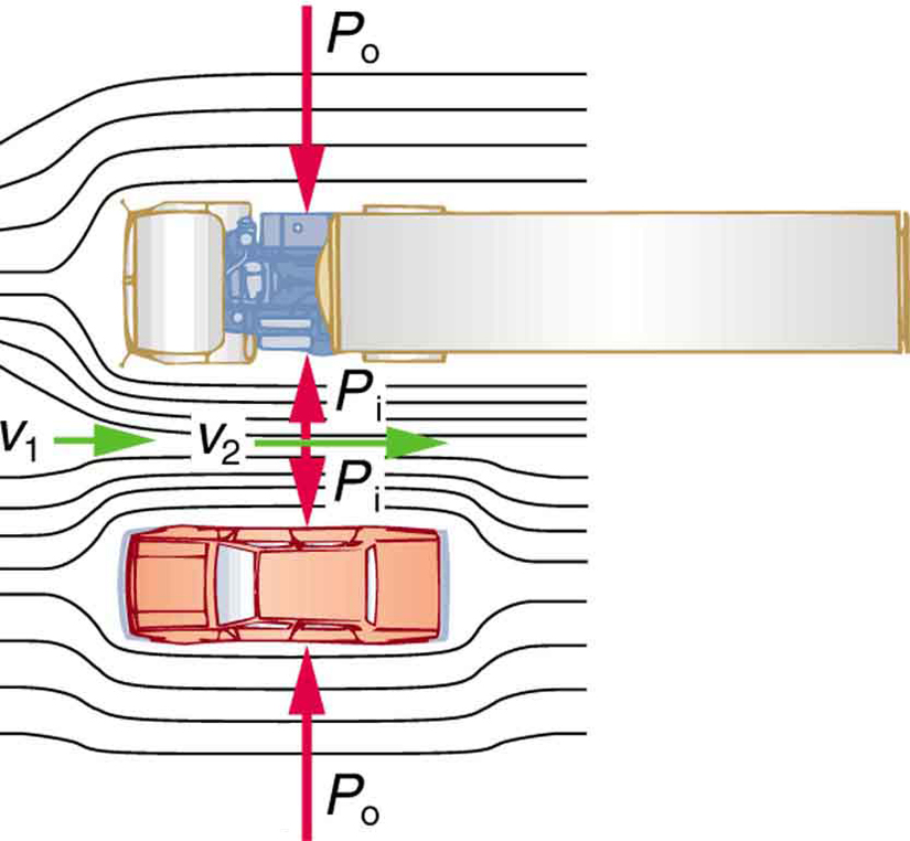
The result is a drop in pressure in a rapidly moving fluid, whether or not the fluid is confined to a tube. This principle has many real-world implications. For example, when you take a shower, the fast-moving water and air lower the pressure inside the shower stall, causing the curtain to bulge inward. Similarly, when a car passes a large truck, air velocity increases in the narrow space between the two vehicles. According to Bernoulli’s principle, this results in lower pressure between the car and truck, causing them to be pushed together due to the higher external pressure.
This effect is illustrated in Figure 86.1:
Take-Home Investigation
Try this simple experiment: Hold a sheet of paper by its short edge so that it slants downward from your mouth. Blow across the top of the sheet. You’ll see the paper lift. This occurs because your fast-moving breath lowers the air pressure above the sheet, while the pressure below remains higher, lifting the paper upward—just as Bernoulli’s principle predicts.
Bernoulli’s Equation
The mathematical form of Bernoulli’s principle is known as Bernoulli’s equation, named after Swiss scientist Daniel Bernoulli. It expresses the conservation of energy in a fluid system without friction:
Here:
- [latex]P[/latex] is the absolute pressure
- [latex]\rho[/latex] is the fluid density
- [latex]v[/latex] is the velocity of the fluid
- [latex]g[/latex] is the acceleration due to gravity
- [latex]h[/latex] is the vertical height above a reference point
Following a specific fluid element along its path, this sum remains constant if the fluid is incompressible and experiences no friction. Between any two points along the flow path, Bernoulli’s equation becomes:
Bernoulli’s Equation and Energy Conservation
Bernoulli’s equation is essentially a statement of the conservation of energy. Each term in the equation represents energy per unit volume:
- Pressure energy: [latex]P[/latex]
- Kinetic energy per unit volume: [latex]\frac{1}{2} \rho v^2[/latex]
- Gravitational potential energy per unit volume: [latex]\rho gh[/latex]
Let’s verify that each term has units of energy per volume. For example, kinetic energy per unit volume:
Similarly, for gravitational potential energy:
Pressure has units of force per area: [latex]P = F/A[/latex]. Multiply by length ([latex]m/m[/latex]) to get [latex]\text{N}\cdot\text{m}/\text{m}^3 = \text{J}/\text{m}^3[/latex], which is energy per unit volume.
Bernoulli’s Equation in Static Fluids
Let’s apply Bernoulli’s equation to static (non-moving) fluids. In this case, [latex]v_1 = v_2 = 0[/latex], and the equation simplifies to:
Choosing [latex]h_2 = 0[/latex] as the reference height gives:
This form tells us that pressure increases with depth in a static fluid. This relationship is familiar in physiology, where blood pressure increases slightly with depth in the body, such as between the arm and the ankle.
Bernoulli’s Principle: Constant Depth Flow
In many biological applications, such as horizontal blood flow through arteries, the vertical height remains constant ([latex]h_1 = h_2[/latex]). In that case, Bernoulli’s equation reduces to:
This is called Bernoulli’s principle and shows that pressure decreases where speed increases in a fluid flow. This is particularly important in clinical settings such as blood flow through narrowed arteries, where the velocity increases and the pressure drops—an effect central to Doppler ultrasound diagnostics and understanding conditions like arterial stenosis.
Example 86.1 Calculating Pressure: Pressure Drops as a Fluid Speeds Up
In Example 85.2, we found that the speed of water in a hose increased from 1.96 m/s to 25.5 m/s going from the hose to the nozzle. Calculate the pressure in the hose, given that the absolute pressure in the nozzle is [latex]1\text{.}\text{01}×{\text{10}}^{5}\phantom{\rule{0.25em}{0ex}}{\text{N/m}}^{2}[/latex] (atmospheric, as it must be) and assuming level, frictionless flow.
Strategy
Level flow means constant depth, so Bernoulli’s principle applies. We use the subscript 1 for values in the hose and 2 for those in the nozzle. We are thus asked to find [latex]{P}_{1}[/latex].
Solution
Solving Bernoulli’s principle for [latex]{P}_{1}[/latex] yields
Substituting known values,
Discussion
This absolute pressure in the hose is greater than in the nozzle, as expected since [latex]v[/latex] is greater in the nozzle. The pressure [latex]{P}_{2}[/latex] in the nozzle must be atmospheric since it emerges into the atmosphere without other changes in conditions.
Applications of Bernoulli’s Principle
Bernoulli’s principle helps us understand a wide range of biological and technological systems where fluid flows at a constant height. In this section, we examine several real-world applications of this principle, particularly focusing on how it connects to the behavior of air and liquid flows in engineered and natural systems.
Entrainment
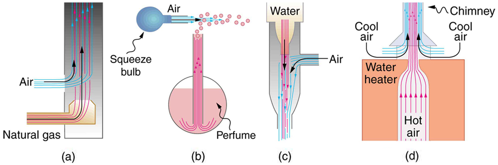
Entrainment refers to the process where a high-speed fluid stream draws in another fluid due to the lower pressure it creates. This concept has been used for centuries in technologies designed to move fluids, such as pumps for draining swamps or fields. When a jet of fast-moving fluid creates a low-pressure region, surrounding fluids are pulled into the stream, as illustrated in Figure 86.2.
Examples of entrainment devices include:
- Bunsen burners that mix gas and air efficiently for combustion;
- Atomizers that draw perfume or paint into an airstream;
- Aspirators that use water flow to generate suction, commonly used in medical or lab equipment;
- Water heater chimneys designed to draw cool air into rising warm exhaust for improved ventilation.
Each of these devices uses a high-velocity fluid to create a lower pressure region that entrains another fluid.
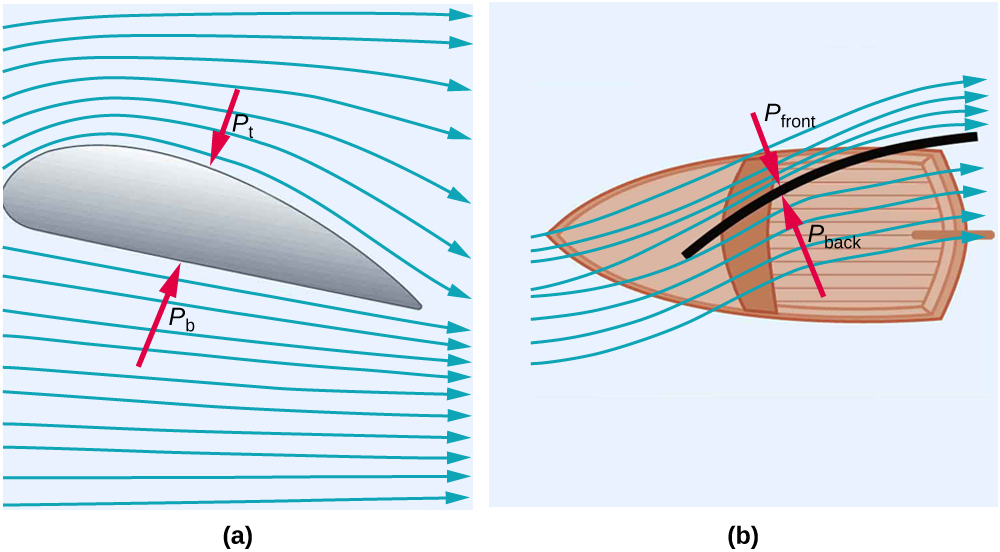
Wings and Sails
Airplane wings and boat sails are classic examples of Bernoulli’s principle in action. The characteristic curved shape of a wing causes air to travel faster over the top surface than underneath, creating a pressure difference. The lower pressure on top leads to an upward lift force (Figure 86.3(a)). Similarly, a sail is shaped like a wing and exploits pressure differences to generate forward motion—even allowing travel into the wind (Figure 86.3(b)).
Take-Home Activity: Two Strips of Paper
Try holding two strips of paper (about 15 cm long and 4 cm wide) up to your lips, separated by your fingers. Blow between the strips. What do you observe? This simple activity demonstrates Bernoulli’s principle in action.
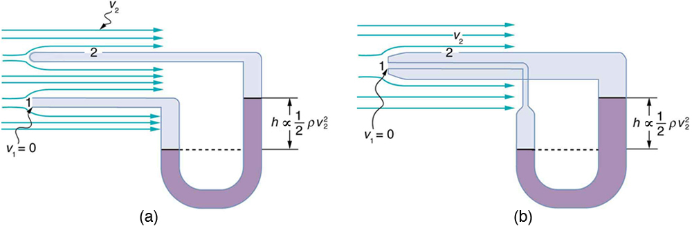
Velocity Measurement
Bernoulli’s principle is also applied to measure fluid speed. One common method uses a manometer connected to two tubes placed in a fluid stream. As shown in Figure 86.4(a), one tube faces the flow directly, causing a “dead spot” with velocity [latex]{v}_{1} = 0[/latex], while the other is aligned with the flow ([latex]{v}_{2} \neq 0[/latex]). Using Bernoulli’s principle, the pressure difference between these points is:
This means the fluid in the manometer rises on one side, and the height difference [latex]h[/latex] is proportional to the velocity squared:
Solving for [latex]v_{2}[/latex] gives:
Figure 86.4(b) shows a Prandtl (or Pitot) tube, a common velocity-measuring instrument in aviation and fluid engineering.
Summary
- Bernoulli’s equation for incompressible, frictionless fluids is:
[latex]{P}_{1} + \frac{1}{2} \rho v_{1}^{2} + \rho gh_{1} = {P}_{2} + \frac{1}{2} \rho v_{2}^{2} + \rho gh_{2}[/latex]
- Bernoulli’s principle is a simplified version of Bernoulli’s equation for cases where height is constant:
[latex]{P}_{1} + \frac{1}{2} \rho v_{1}^{2} = {P}_{2} + \frac{1}{2} \rho v_{2}^{2}[/latex]
- This principle helps explain phenomena like entrainment, aerodynamic lift in wings and sails, and is used in devices that measure fluid velocity.
Conceptual Questions
- You can squirt water a considerably greater distance by placing your thumb over the end of a garden hose and then releasing, than by leaving it completely uncovered. Explain how this works.
- Water is shot nearly vertically upward in a decorative fountain and the stream is observed to broaden as it rises. Conversely, a stream of water falling straight down from a faucet narrows. Explain why, and discuss whether surface tension enhances or reduces the effect in each case.
- Look back to Figure 86.1. Answer the following two questions. Why is [latex]{P}_{\text{o}}[/latex] less than atmospheric? Why is [latex]{P}_{\text{o}}[/latex] greater than [latex]{P}_{\text{i}}[/latex]?
- Give an example of entrainment not mentioned in the text.
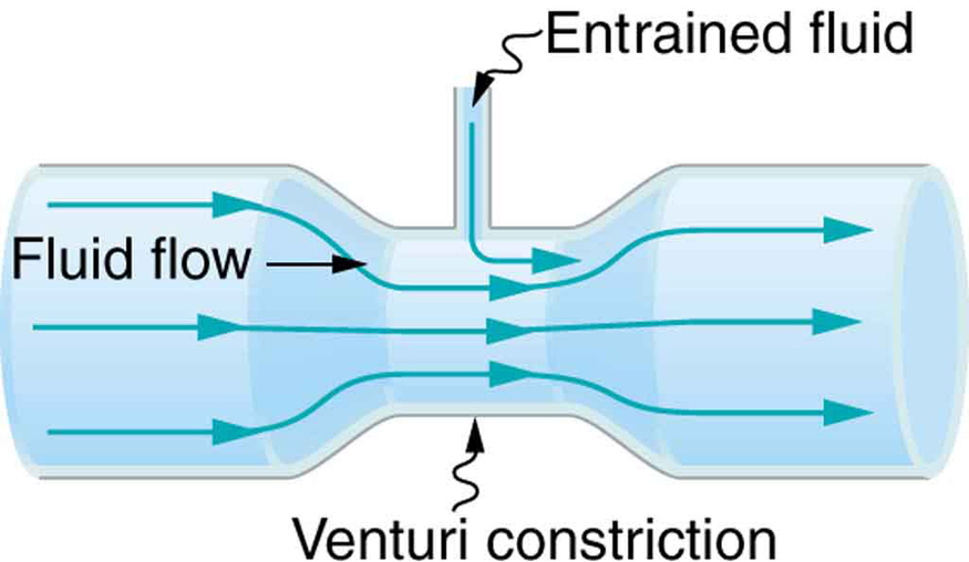 Figure 86.5 A tube with a narrow segment designed to enhance entrainment is called a Venturi. These are very commonly used in carburetors and aspirators.
 - Many entrainment devices have a constriction, called a Venturi, such as shown in Figure 86.5. How does this bolster entrainment?
- Some chimney pipes have a T-shape, with a crosspiece on top that helps draw up gases whenever there is even a slight breeze. Explain how this works in terms of Bernoulli’s principle.
- Is there a limit to the height to which an entrainment device can raise a fluid? Explain your answer.
- Why is it preferable for airplanes to take off into the wind rather than with the wind?
- Roofs are sometimes pushed off vertically during a tropical cyclone, and buildings sometimes explode outward when hit by a tornado. Use Bernoulli’s principle to explain these phenomena.
- Why does a sailboat need a keel?
- It is dangerous to stand close to railroad tracks when a rapidly moving commuter train passes. Explain why atmospheric pressure would push you toward the moving train.
- Water pressure inside a hose nozzle can be less than atmospheric pressure due to the Bernoulli effect. Explain in terms of energy how the water can emerge from the nozzle against the opposing atmospheric pressure.
- A perfume bottle or atomizer sprays a fluid that is in the bottle. (Figure 86.6.) How does the fluid rise up in the vertical tube in the bottle?
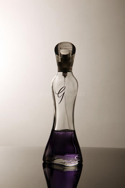
Figure 86.6 Atomizer: perfume bottle with tube to carry perfume up through the bottle. (credit: Antonia Foy, Flickr) - If you lower the window on a car while moving, an empty plastic bag can sometimes fly out the window. Why does this happen?
Problems & Exercises
- Verify that pressure has units of energy per unit volume.
- Suppose you have a wind speed gauge like the pitot tube shown in Figure 86.4(b). By what factor must wind speed increase to double the value of [latex]h[/latex] in the manometer? Is this independent of the moving fluid and the fluid in the manometer?
- If the pressure reading of your pitot tube is 15.0 mm Hg at a speed of 200 km/h, what will it be at 700 km/h at the same altitude?
- Calculate the maximum height to which water could be squirted with the hose in Example 85.2 if it: (a) Emerges from the nozzle. (b) Emerges with the nozzle removed, assuming the same flow rate.
- Every few years, winds in Boulder, Colorado, attain sustained speeds of 45.0 m/s (about 100 mi/h) when the jet stream descends during early spring. Approximately what is the force due to the Bernoulli effect on a roof having an area of [latex]\text{220}\phantom{\rule{0.25em}{0ex}}{\text{m}}^{2}[/latex]? Typical air density in Boulder is [latex]1\text{.}\text{14}\phantom{\rule{0.25em}{0ex}}{\text{kg/m}}^{3}[/latex], and the corresponding atmospheric pressure is [latex]8\text{.}\text{89}×{\text{10}}^{4}\phantom{\rule{0.25em}{0ex}}{\text{N/m}}^{2}[/latex]. (Bernoulli’s principle as stated in the text assumes laminar flow. Using the principle here produces only an approximate result, because there is significant turbulence.)
- (a) Calculate the approximate force on a square meter of sail, given the horizontal velocity of the wind is 6.00 m/s parallel to its front surface and 3.50 m/s along its back surface. Take the density of air to be [latex]\text{1.29 kg}{\text{/m}}^{3}[/latex]. (The calculation, based on Bernoulli’s principle, is approximate due to the effects of turbulence.) (b) Discuss whether this force is great enough to be effective for propelling a sailboat.
- (a) What is the pressure drop due to the Bernoulli effect as water goes into a 3.00-cm-diameter nozzle from a 9.00-cm-diameter fire hose while carrying a flow of 40.0 L/s? (b) To what maximum height above the nozzle can this water rise? (The actual height will be significantly smaller due to air resistance.)
- (a) Using Bernoulli’s equation, show that the measured fluid speed [latex]v[/latex] for a pitot tube, like the one in Figure 86.4(b), is given by [latex]v = \sqrt{\dfrac{2\rho' g h}{\rho}}[/latex] where [latex]h[/latex] is the height of the manometer fluid, [latex]\rho'[/latex] is the density of the manometer fluid, [latex]\rho[/latex] is the density of the moving fluid, and [latex]g[/latex] is the acceleration due to gravity. (Note that [latex]v[/latex] is indeed proportional to the square root of [latex]h[/latex], as stated in the text.)(b) Calculate [latex]v[/latex] for moving air if a mercury manometer’s [latex]h[/latex] is 0.200 m.
Glossary
- Bernoulli’s equation
- the equation resulting from applying conservation of energy to an incompressible frictionless fluid: P + 1/2pv2 + pgh = constant, through the fluid
- Bernoulli’s principle
- Bernoulli’s equation applied at constant depth: P1 + 1/2pv12 = P2 + 1/2pv22
Bernoulli’s equation applied at constant depth: P1 + 1/2pv12 = P2 + 1/2pv22
the equation resulting from applying conservation of energy to an incompressible frictionless fluid: P + 1/2pv2 + pgh = constant, through the fluid
the rule that the sum of the kinetic energies and potential energies remains constant if only conservative forces act on and within a system
