
Magnetism
40 Magnetic Force on a Current-Carrying Conductor
Learning Objectives
- Describe how a magnetic field exerts a force on a current-carrying conductor.
- Calculate the magnetic force acting on a current-carrying conductor.
In the previous sections, we learned that a magnetic field exerts a force on an individual moving charge. In most practical situations, however, charges move through a metal wire or another conductor rather than freely through space. Because these charges are confined within the conductor, the magnetic force acting on each charge is transmitted to the conductor itself. As a result, an entire wire carrying current can experience a measurable force.
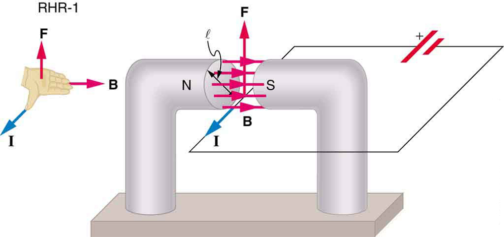
This principle is the foundation of many technologies, including electric motors, loudspeakers, and magnetic actuators used in medical devices such as infusion pumps and surgical instruments. In each case, electrical energy is converted into mechanical motion through the interaction between an electric current and a magnetic field.
To derive the magnetic force on a current-carrying wire, we begin with the magnetic force on a single moving charge:
where [latex]q[/latex] is the charge, [latex]v_d[/latex] is the drift velocity of the charge carriers, [latex]B[/latex] is the magnetic field strength, and [latex]\theta[/latex] is the angle between the direction of motion and the magnetic field.
If the magnetic field is uniform over a length [latex]l[/latex] of wire, every charge carrier in that section experiences a force in the same direction. Therefore, the total magnetic force is the sum of the forces on all the moving charges:
where [latex]N[/latex] is the number of charge carriers within the portion of wire inside the magnetic field.
The number of charge carriers can be written as
where [latex]n[/latex] is the number of charge carriers per unit volume and [latex]V[/latex] is the volume of the wire exposed to the field. Since the volume of this section is
where [latex]A[/latex] is the wire's cross-sectional area, the force becomes
Rearranging the terms gives
From our earlier study of electric current, we know that
where [latex]I[/latex] is the electric current. Substituting this relationship into the previous expression leads to one of the fundamental equations of electromagnetism:
This equation gives the magnitude of the magnetic force acting on a straight wire of length [latex]l[/latex] carrying a current [latex]I[/latex] in a uniform magnetic field [latex]B[/latex]. The force is greatest when the current is perpendicular to the magnetic field ([latex]\theta=90^\circ[/latex]) and becomes zero when the current flows parallel to the field.
Sometimes it is useful to know the force acting on each meter of wire. Dividing the previous equation by the wire length gives
The direction of the magnetic force is determined using Right-Hand Rule 1 (RHR-1). Point your right thumb in the direction of the conventional current, extend your fingers in the direction of the magnetic field, and your palm points in the direction of the magnetic force acting on the wire.
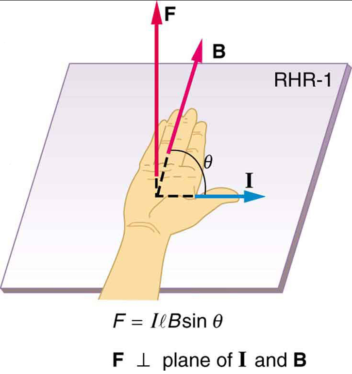
Example 40.1: Calculating the Magnetic Force on a Current-Carrying Wire
A straight wire carrying an electric current passes through a uniform magnetic field, as shown in Figure 40.1. Calculate the magnitude of the magnetic force acting on the wire if the magnetic field strength is [latex]B=1.50\ \text{T}[/latex], the length of wire within the field is [latex]l=5.00\ \text{cm}[/latex], and the current is [latex]I=20.0\ \text{A}[/latex].
Strategy
The magnetic force on a current-carrying wire is given by
In this example, the current is perpendicular to the magnetic field, so the angle between them is [latex]\theta=90^\circ[/latex]. Therefore, [latex]\sin\theta=1[/latex], and the equation simplifies to
Solution
First, convert the wire length to SI units:
Now substitute the known values into the magnetic force equation:
Discussion
A force of 1.50 N is surprisingly large considering that only 5.00 cm of wire is inside the magnetic field. This illustrates why magnetic forces are so useful in electrical devices. By controlling the current and magnetic field, engineers can generate predictable mechanical forces to move wires, coils, or entire machines.
This principle is fundamental to the operation of electric motors, loudspeakers, MRI gradient coils, and many types of laboratory and medical equipment.
The magnetic force acting on current-carrying conductors provides a direct way to convert electrical energy into mechanical motion. Electric motors are the most familiar example, using loops of wire that rotate when placed in magnetic fields. Another interesting application is magnetohydrodynamics (MHD), which uses magnetic forces to move electrically conducting fluids without any moving mechanical parts.
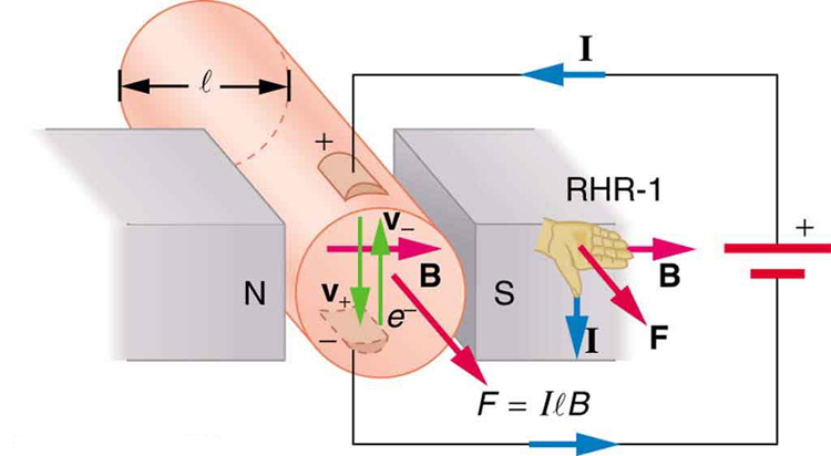
In an MHD pump, a strong magnetic field is applied across a tube while an electric current passes through the conducting fluid. According to the magnetic force equation, the fluid experiences a force parallel to the tube and begins to flow. Since there are no moving blades or valves, MHD pumps are particularly useful for transporting hot or chemically reactive liquids, such as the liquid sodium used as a coolant in some advanced nuclear reactors.
Researchers have also investigated MHD technology for biomedical applications. For example, experimental artificial heart pumps have explored using magnetic forces to move blood without mechanical impellers, potentially reducing wear and improving long-term reliability. However, the strong magnetic fields required can affect living cells and tissues, making this application technically challenging.
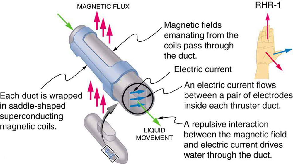
MHD propulsion has also been proposed for submarines. Instead of using a rotating propeller, an MHD drive accelerates seawater directly using magnetic forces, producing thrust with much less mechanical noise. A quieter propulsion system could make submarines more difficult to detect. Although this concept has attracted considerable research interest, current MHD propulsion systems remain relatively heavy and inefficient compared with conventional propellers.
Section Summary
- The magnetic force on a current-carrying conductor in a uniform magnetic field is given by
[latex]F=IlB\sin\theta[/latex]
where [latex]I[/latex] is the current, [latex]l[/latex] is the length of the conductor within the magnetic field, [latex]B[/latex] is the magnetic field strength, and [latex]\theta[/latex] is the angle between the current and the magnetic field.
- The direction of the magnetic force is determined using Right-Hand Rule 1 (RHR-1): point your right thumb in the direction of the conventional current, point your fingers in the direction of the magnetic field, and your palm points in the direction of the force.
Conceptual Questions
- Draw a sketch similar to Figure 40.1, showing the direction in which electrons move through the wire. Then use Right-Hand Rule 1 (RHR-1) to verify the direction of the magnetic force acting on the wire.
- Using Figure 40.3, explain why the direction of the magnetic force in a magnetohydrodynamic (MHD) pump is the same regardless of whether the current is carried by positive or negative charges.
- Why would a magnetohydrodynamic (MHD) propulsion system operate more effectively in seawater than in freshwater? Why would superconducting magnets improve the performance of such a system?
- Which is more likely to interfere with the reading of a nearby compass: the alternating current (AC) used by a household refrigerator or the direct current (DC) drawn by a car's starter motor during engine startup? Explain your reasoning.
Problems & Exercises
- Determine the direction of the magnetic force acting on the current in each of the six cases shown in Figure 40.5.
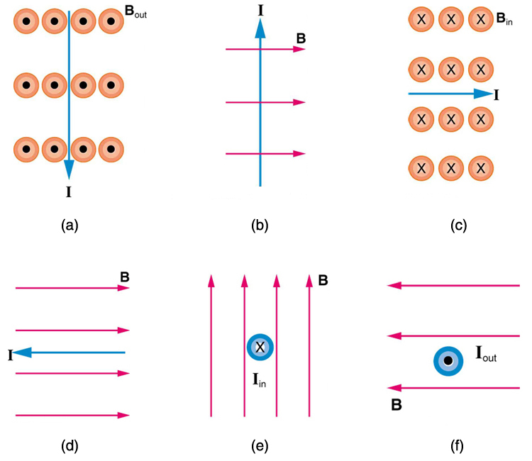
Figure 40.5: Use the right-hand rule to determine the direction of the magnetic force in each case. - Determine the direction of the current in each of the three cases shown in Figure 40.6. Assume that the current is perpendicular to the magnetic field.
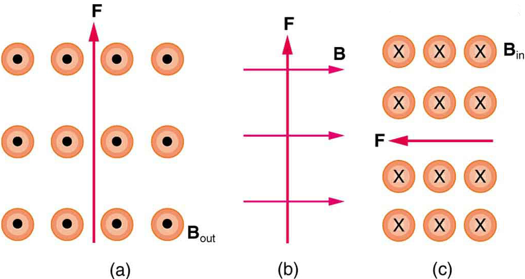
Figure 40.6: Use the right-hand rule to determine the direction of the current in each case. - Determine the direction of the magnetic field in each of the three cases shown in Figure 40.7. Assume that the magnetic field is perpendicular to the current.
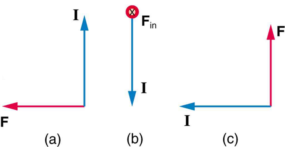
Figure 40.7: Use the right-hand rule to determine the direction of the magnetic field in each case. - A lightning bolt at the equator carries a current of 20,000 A perpendicular to Earth's [latex]3.00\times10^{-5}\,\text{T}[/latex] magnetic field.
- What is the magnetic force per meter of the lightning bolt?
- What is the direction of the force if the current points vertically upward and Earth's magnetic field points due north, parallel to the ground?
- A direct-current power line for a light-rail system carries 1000 A at an angle of [latex]30.0^\circ[/latex] to Earth's [latex]5.00\times10^{-5}\,\text{T}[/latex] magnetic field.
- What magnetic force acts on a 100-m section of the power line?
- Discuss whether this force presents any significant practical concern.
- An MHD drive uses a tube with a diameter of 25.0 cm. A current of 100 A passes across the tube perpendicular to a 2.00-T magnetic field. What force is exerted on the water inside the tube? (Note: The relatively small force illustrates why practical MHD drives require very large currents and strong magnetic fields.)
- A wire carrying a 30.0-A current passes between the poles of a strong magnet. The current is perpendicular to the magnetic field, and a 4.00-cm section of the wire experiences a force of 2.16 N. What is the average magnetic field strength?
- A 0.750-m section of cable carries current to a car's starter motor and makes an angle of [latex]60.0^\circ[/latex] with Earth's [latex]5.50\times10^{-5}\,\text{T}[/latex] magnetic field.
- What current flows through the cable if it experiences a magnetic force of [latex]7.00\times10^{-3}\,\text{N}[/latex]?
- The same cable is placed between the poles of a strong horseshoe magnet so that 5.00 cm of the cable is perpendicular to a 1.75-T magnetic field. What force acts on this section of cable?
- A 50.0-cm section of wire carries a current of 8.00 A in a 1.20-T magnetic field and experiences a magnetic force of 2.40 N.
- What is the angle between the current and the magnetic field?
- What force would act on the wire if it were rotated so that the current made an angle of [latex]90.0^\circ[/latex] with the field?
- The rectangular current loop shown in Figure 40.8 can be used to measure magnetic field strength. The magnetic field is uniform in the shaded region and zero outside it. The plane of the loop is perpendicular to the field.
- Determine the direction of the net magnetic force on the loop. Explain why the forces on the two vertical sides are equal and opposite, regardless of how much of those sides lies within the magnetic field, and therefore do not contribute to the net force.
- If the current is 5.00 A, what is the force per tesla acting on the 20.0-cm-wide horizontal section of the loop?
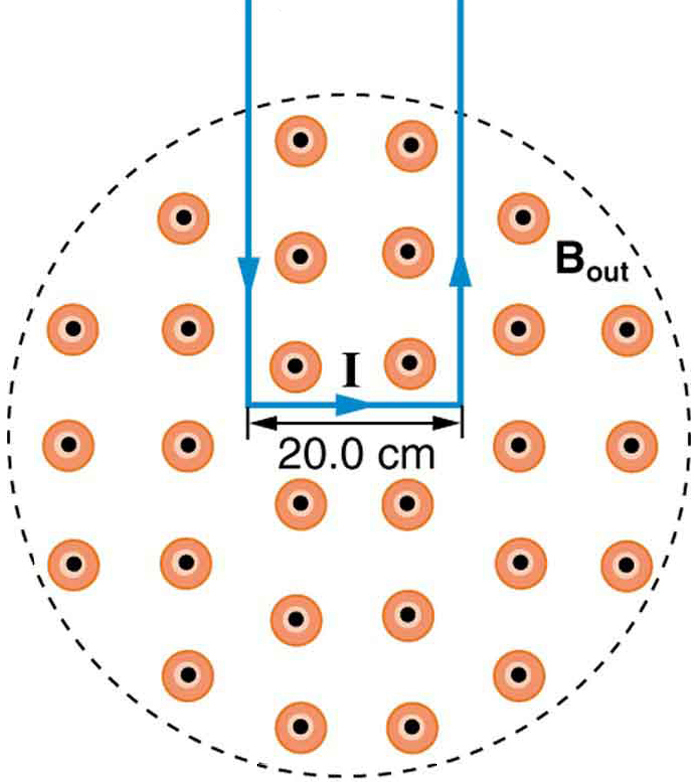
Figure 40.8: A rectangular current loop lies partly inside a region of uniform magnetic field. The field points out of the page and is zero outside the shaded region.
Glossary
- magnetohydrodynamics (MHD)
- The use of magnetic fields and electric currents to control or move electrically conducting fluids without moving mechanical parts.
The use of magnetic fields and electric currents to control or move electrically conducting fluids without moving mechanical parts.
