
Magnetism
43 Magnetic Force between Two Parallel Conductors
Learning Objectives
- Describe the magnetic force between two current-carrying conductors.
- Calculate the force between two parallel current-carrying conductors.
Current-carrying wires not only produce magnetic fields—they also exert magnetic forces on one another. These forces are responsible for the operation of many electrical devices and become especially important whenever very large currents are present. For example, they influence the design of power transmission systems, electric motors, MRI magnets, and high-current laboratory equipment. They also explain why large electrical circuit breakers must withstand enormous mechanical forces when interrupting high-current faults.
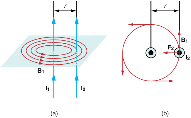
Consider two long, straight, parallel conductors separated by a distance [latex]r[/latex], as shown in Figure 43.1. Each wire produces a magnetic field that acts on the current flowing through the other wire. The magnetic field produced by wire 1 at the location of wire 2 is
Because this magnetic field is perpendicular to wire 2, the magnetic force on a length [latex]l[/latex] of the wire is
According to Newton's third law, wire 2 exerts an equal and opposite force on wire 1. Since these wires are assumed to be very long, it is convenient to express the result as a force per unit length. Substituting the expression for [latex]B_1[/latex] gives
where [latex]I_1[/latex] and [latex]I_2[/latex] are the currents in the two conductors and [latex]r[/latex] is the distance between them.
The direction of the force depends on the direction of the currents:
- If the currents flow in the same direction, the wires attract each other.
- If the currents flow in opposite directions, the wires repel each other.
These magnetic forces are responsible for the pinch effect, in which parallel currents attract one another and become concentrated into a narrower region. The pinch effect occurs in electric arcs, plasmas, and many laboratory fusion experiments. It can also occur inside high-power electrical switches and circuit breakers, where intense currents produce strong magnetic forces that compress electric arcs and may damage the equipment if not properly controlled.
Historically, the force between two parallel current-carrying wires played an important role in defining the unit of electric current. For two wires separated by 1.00 m and each carrying a current of 1.00 A, the force per unit length is
Historical Note: The Ampere
Before 2019, the SI unit of electric current (the ampere) was defined using the magnetic force between two long, parallel current-carrying conductors. Today, the ampere is defined by fixing the value of the elementary charge,
making the definition independent of any specific experimental setup. Nevertheless, the force between parallel currents remains one of the most important demonstrations of the relationship between electricity and magnetism and provides an accurate method for measuring electrical currents.
Although infinitely long wires cannot be constructed in practice, highly precise instruments called current balances use carefully designed coils to measure the tiny magnetic forces produced by electric currents. These measurements can be used to determine current with exceptional accuracy. Once the current is known, the amount of electric charge transferred during a given time interval follows directly from
For example, a current of 1.00 A flowing for 1.00 s transfers a charge of
Section Summary
- The magnetic force per unit length between two long, parallel current-carrying conductors is
[latex]\frac{F}{l}=\frac{\mu_0 I_1 I_2}{2\pi r}[/latex]
where [latex]I_1[/latex] and [latex]I_2[/latex] are the currents in the conductors, [latex]r[/latex] is the distance between them, and [latex]\mu_0[/latex] is the permeability of free space.
- Parallel currents flowing in the same direction attract each other, whereas currents flowing in opposite directions repel each other.
- The magnetic attraction between parallel currents is responsible for the pinch effect, which occurs in electric arcs, plasmas, and other high-current systems.
Conceptual Questions
- Is the magnetic force between the hot and neutral wires on an overhead power line attractive or repulsive? Explain your reasoning based on the direction of the currents in the two wires.
- Suppose three long, parallel wires lie in the same plane, as shown in Figure 43.2, with the currents in the two outer wires flowing in opposite directions.
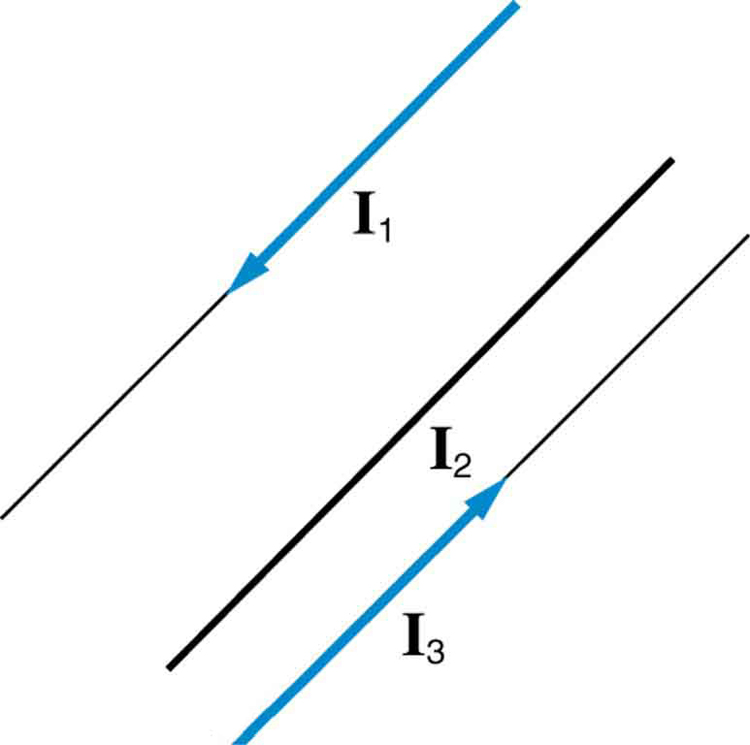
Figure 43.2: Three parallel coplanar wires with currents in the outer two flowing in opposite directions. Is it possible for the middle wire to be repelled by both outer wires? Could it instead be attracted by both? Explain your reasoning.
- Suppose two long, straight wires cross each other at right angles without touching. Does either wire exert a net force on the other? If so, what is its direction? Does either wire exert a net torque on the other? Use the appropriate right-hand rules to justify your answers.
- Use the right-hand rules to show that the force between the two current loops in Figure 43.3 is attractive when the currents flow in the same direction and repulsive when they flow in opposite directions. Is this behavior consistent with the interaction between the north and south poles of two bar magnets? Support your explanation with sketches.
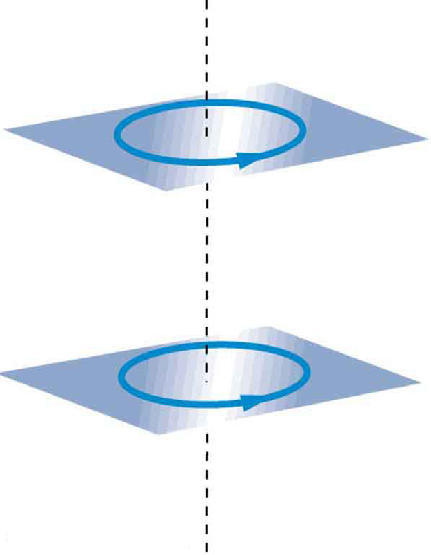
Figure 43.3: Two current-carrying loops can exert both magnetic forces and torques on one another. - If one of the loops in Figure 43.3 is tilted slightly while the currents flow in the same direction, what torques do the loops exert on each other? Based on your answer, would you expect the loops to rotate until their magnetic fields become aligned?
- Electric fields can be shielded using a Faraday cage. Can magnetic fields also be shielded? What about gravitational fields? Explain your reasoning.
Problems & Exercises
- A light-rail commuter train is powered by two long, parallel conductors carrying a direct current of 800 A. The conductors are separated by 75.0 cm.
- Calculate the magnitude and direction of the magnetic force between a 50.0-m section of these conductors.
- Discuss whether this force has any important practical consequences for the design or operation of the power system.
- The force per unit length between the two wires of a jumper cable used to start a stalled car is 0.225 N/m.
- What current flows in the wires if they are separated by 2.00 cm?
- Is the magnetic force between the wires attractive or repulsive?
- A 2.50-m-long wire supplying current to the motor of a submerged submarine carries 1000 A. It experiences a 4.00-N repulsive force from a parallel wire located 5.00 cm away. Determine the magnitude and direction of the current in the second wire.
- A wire carrying 400 A to the motor of a commuter train experiences an attractive force of [latex]4.00\times10^{-3}\ \text{N/m}[/latex] due to a nearby parallel wire carrying 5.00 A to a headlight.
- How far apart are the two wires?
- Are the currents flowing in the same direction or in opposite directions?
- An AC appliance cord has its hot and neutral wires separated by 3.00 mm and carries a current of 5.00 A.
- What is the average magnetic force per meter between the two wires?
- What is the maximum force per meter between the wires?
- During the AC cycle, are the forces attractive or repulsive?
- Do appliance cords require any special design features to compensate for these magnetic forces? Explain.
- A long, straight wire is located near a rectangular current loop, as shown in Figure 43.4. Determine both the magnitude and the direction of the total magnetic force acting on the loop.
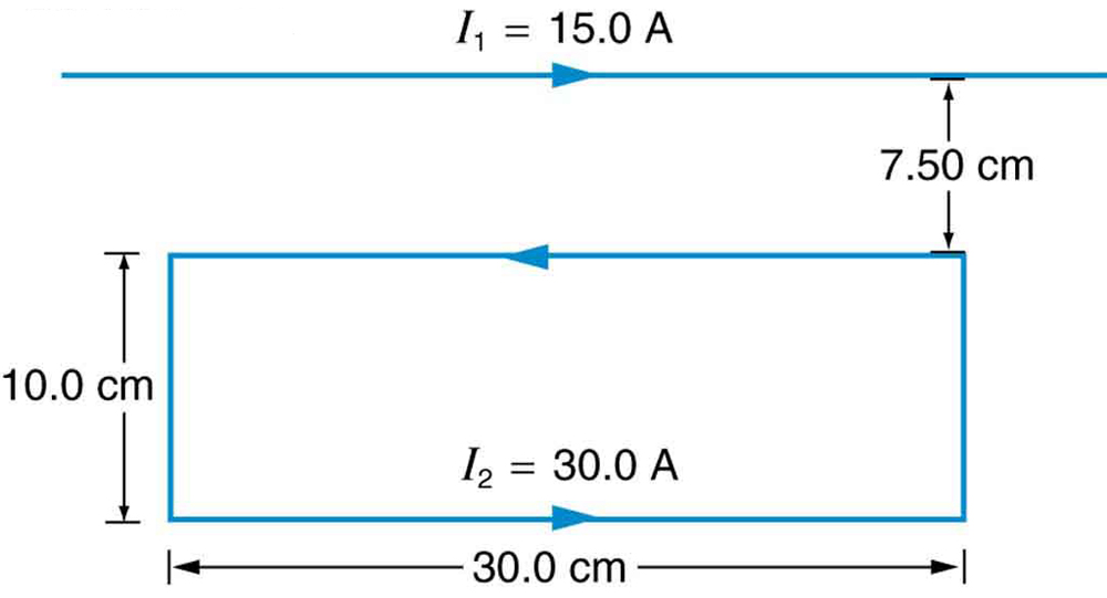
Figure 43.4: A rectangular current loop placed near a long straight current-carrying wire. - Determine the magnitude and direction of the magnetic force acting on each wire in Figure 43.5(a) by using vector addition.
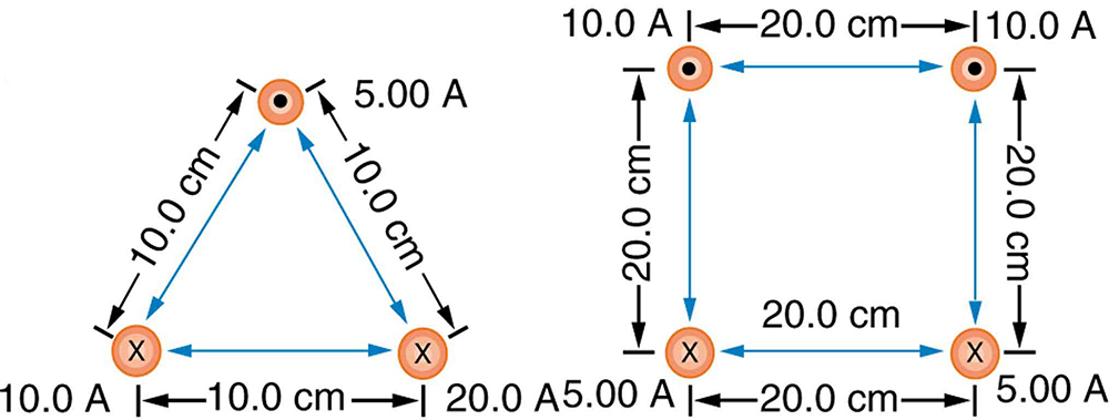
Figure 43.5: Parallel current-carrying wires exert magnetic forces on one another. - Using vector addition, determine the magnitude and direction of the magnetic force acting on each wire in Figure 43.5(b).
Glossary
- force per unit length between parallel conductors
- The magnetic force per unit length between two long, parallel current-carrying wires separated by a distance
[latex]r[/latex], given by
[latex]\frac{F}{l}=\frac{\mu_0 I_1 I_2}{2\pi r}[/latex].
- parallel conductors
- Two or more current-carrying wires that run alongside one another. Their magnetic fields interact, producing attractive or repulsive forces depending on the directions of the currents.
- attractive magnetic force
- The magnetic force that occurs between two parallel conductors when the currents flow in the same direction, causing the wires to pull toward one another.
- repulsive magnetic force
- The magnetic force that occurs between two parallel conductors when the currents flow in opposite directions, causing the wires to push away from one another.
- pinch effect
- The tendency of parallel electric currents in a plasma or electric arc to attract one another, compressing the current into a narrower region due to magnetic forces.
- ampere (operational definition)
- Historically defined as the current that, when flowing through each of two infinitely long parallel conductors separated by 1 m in vacuum, produces a magnetic force of exactly
[latex]2.0\times10^{-7}\ \text{N/m}[/latex]
between the conductors.
Two or more current-carrying wires that run alongside one another. Their magnetic fields interact, producing attractive or repulsive forces depending on the directions of the currents.
The magnetic force per unit length between two long, parallel current-carrying wires separated by a distance
[latex]r[/latex], given by
[latex]\frac{F}{l}=\frac{\mu_0 I_1 I_2}{2\pi r}[/latex].
The magnetic force that occurs between two parallel conductors when the currents flow in the same direction, causing the wires to pull toward one another.
The magnetic force that occurs between two parallel conductors when the currents flow in opposite directions, causing the wires to push away from one another.
The tendency of parallel electric currents in a plasma or electric arc to attract one another, compressing the current into a narrower region due to magnetic forces.
Historically defined as the current that, when flowing through each of two infinitely long parallel conductors separated by 1 m in vacuum, produces a magnetic force of exactly
[latex]2.0\times10^{-7}\ \text{N/m}[/latex]
between the conductors.
