
Circuits and DC Instruments
32 DC Circuits Containing Resistors and Capacitors
Learning Objectives
- Explain the significance of the RC time constant (τ) and calculate it for a circuit containing a resistor and a capacitor.
- Describe why batteries gradually recharge capacitors more slowly as they age and how this affects electronic devices.
- Interpret graphs showing how the voltage across a capacitor changes during charging and discharging.
- Explain how RC circuits are used as timing devices in electronics and biomedical equipment.
- Apply the concept of the RC time constant to analyze applications such as camera flashes, medical devices, and strobe illumination.
Capacitors store electrical energy and release it when needed. Many familiar electronic devices—including camera flashes, cardiac defibrillators, pacemakers, pulse generators, and biomedical instruments—depend on the controlled charging and discharging of capacitors. One common observation is that charging a capacitor often takes much longer than discharging it. For example, a camera flash may require several seconds to recharge but release all of its stored energy in only a tiny fraction of a second. Understanding why this happens is one of the main goals of this section.
RC Circuits
An RC circuit contains both a resistor, R, and a capacitor, C. The resistor limits the flow of current, while the capacitor stores electrical charge and energy. Together, these components determine how quickly electrical energy can be stored or released.
Figure 32.1 shows a simple RC circuit connected to a DC voltage source. Initially, the capacitor is uncharged. As soon as the switch is closed, current begins flowing through the resistor and onto the capacitor plates. One plate accumulates positive charge while the other accumulates an equal amount of negative charge.
As more charge builds up, the electric field between the plates becomes stronger. This creates an increasing voltage across the capacitor that opposes the battery voltage. As a result, the current gradually decreases until it eventually reaches zero. At that point the capacitor is fully charged and no additional charge flows through the circuit.
The voltage across the capacitor is related to the stored charge by
Here, Q is the charge stored on the capacitor and C is its capacitance. At the instant the switch is closed, the capacitor voltage is zero, so the current has its maximum value,
As the capacitor charges, its voltage steadily increases until it equals the battery's emf. At that point there is no longer a potential difference driving current through the resistor, so the current becomes zero. This behavior is also consistent with Kirchhoff's loop rule: the sum of all potential changes around a closed loop must equal zero.
The charging rate depends on the total resistance in the circuit. A smaller resistance allows more current to flow, causing the capacitor to charge more quickly. The total resistance includes not only the external resistor but also the internal resistance of the battery, the connecting wires, and the capacitor itself. This explains why aging batteries often make devices such as camera flashes recharge more slowly—their internal resistance increases over time.
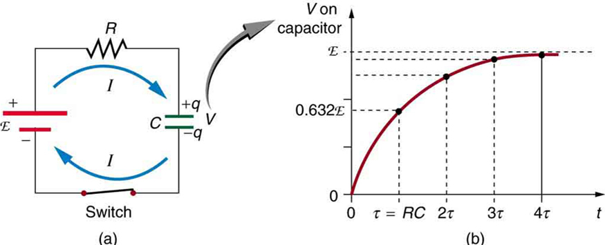
The voltage across the capacitor increases rapidly at first because the current is initially large. As the capacitor becomes charged, the current decreases, so the voltage rises more slowly. The voltage never reaches its final value instantly—instead, it approaches it exponentially.
Using calculus, it can be shown that the voltage across a charging capacitor is
where t is time and e = 2.718... is the base of the natural logarithm.
The product
is called the time constant of the circuit. Since resistance is measured in ohms and capacitance in farads, the product RC has units of seconds.
The time constant provides a convenient way to estimate how quickly the capacitor charges or discharges. A smaller resistance or a smaller capacitance produces a shorter time constant, meaning the circuit responds more quickly. Conversely, larger values of R or C make the charging process slower.
A particularly important point occurs after one time constant has elapsed. Setting t = τ = RC gives
Thus, after one time constant, the capacitor has reached 63.2% of its final voltage.
After two time constants, it reaches approximately 86.5% of its final value; after three, about 95%; and after five time constants, it is more than 99% charged. Mathematically, the capacitor never reaches its final voltage exactly, but after only a few time constants, the remaining difference is so small that, for practical purposes, the capacitor can be considered fully charged.
Exponential charging behavior is not unique to electric circuits. Similar mathematical behavior appears throughout biology and medicine, including the charging of cell membranes, the response of medical sensors, and many physiological processes that gradually approach equilibrium. Understanding the RC time constant therefore provides insight into both electronic devices and biological systems.
Discharging a Capacitor
Charging is only half of the story. Once a capacitor has stored electrical energy, it can release that energy by allowing the stored charge to flow through a circuit. This process is called discharging. Like charging, capacitor discharge does not occur at a constant rate. Instead, both the voltage across the capacitor and the current through the circuit decrease exponentially over time.
Figure 32.2 shows a capacitor connected to a resistor after the voltage source has been removed. When the switch is closed, the electric field stored between the capacitor plates drives current through the resistor. At the instant the discharge begins, the capacitor has its maximum voltage, V0, and therefore produces its largest current:
As charge leaves the capacitor, the voltage across its plates decreases. Since the voltage becomes smaller, the current also decreases. This means that the capacitor discharges rapidly at first and then more slowly as time passes.
Using calculus, the voltage across a discharging capacitor is found to be
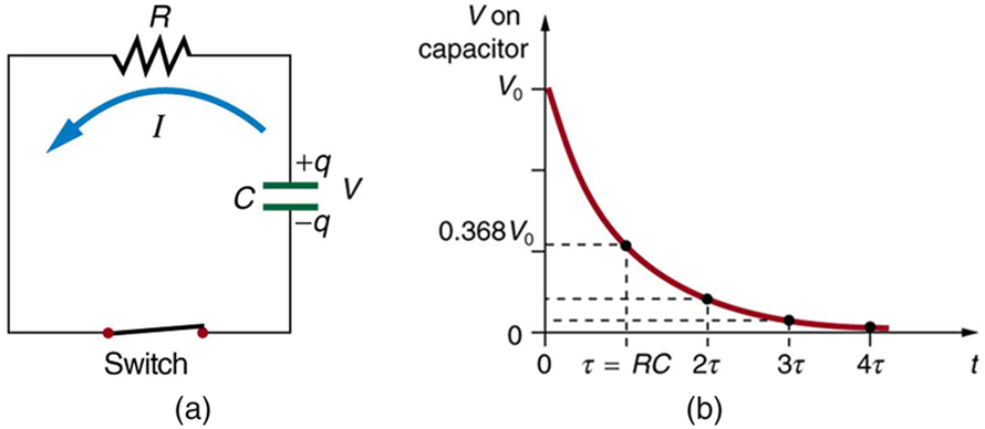
The graph in Figure 32.2(b) illustrates this exponential decay. The same time constant introduced for charging,
also determines how quickly the capacitor discharges. A smaller resistance allows a larger current to flow, causing the capacitor to discharge more rapidly. Likewise, a capacitor with a smaller capacitance stores less charge and therefore empties more quickly.
After one time constant has elapsed, the voltage has decreased to
In other words, after one time constant, only 36.8% of the original voltage remains. After two time constants, the remaining voltage is about 13.5% of its initial value; after three, about 5%; and after five time constants, less than 1% remains. For most practical purposes, the capacitor can be considered fully discharged after approximately five time constants.
The same exponential behavior applies to the current because current is proportional to the capacitor voltage during discharge. Both quantities decrease rapidly at first and then more gradually as the stored energy is depleted.
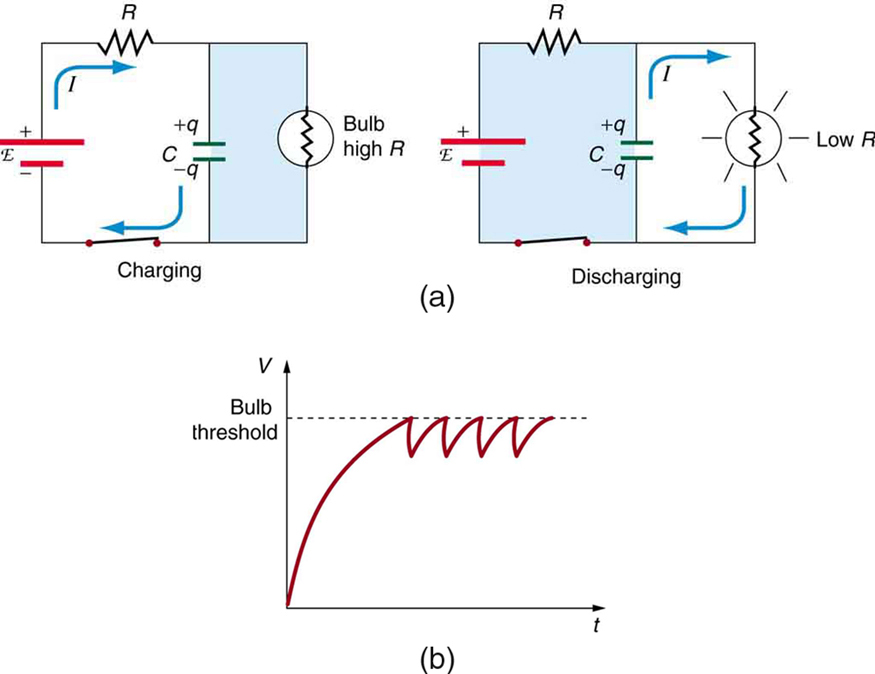
This model explains why devices such as camera flashes recharge much more slowly than they discharge. During charging, the current must pass through the battery and its internal resistance, together with the external circuit resistance. As batteries age, their internal resistance increases, making the charging process progressively slower.
During discharge, however, the capacitor releases its energy through a very low-resistance path. In a camera flash, the discharge occurs through an ionized gas inside the flash tube, allowing nearly all of the stored electrical energy to be released in a tiny fraction of a second.
Extremely short flashes of light are useful because they can "freeze" very fast motion. In medicine and biology, high-speed flashes are used to photograph rapidly moving organisms, analyze muscle contractions, observe insect wing motion, and record fast laboratory experiments. Similar high-intensity flashes are also used to pump energy into certain lasers and in specialized scientific imaging systems.

Example 32.1: Choosing the Capacitor for a High-Speed Strobe Flash
Very short flashes of light are widely used in science, medicine, and engineering to record events that occur too quickly for the human eye to resolve. High-speed flashes can freeze the motion of rapidly moving objects, making it possible to study insect flight, blood droplet formation, mechanical systems, or fast laboratory experiments. The duration of the flash depends on how quickly the capacitor in the flash circuit discharges.
Suppose a high-speed camera is used to photograph a bullet traveling at [latex]5.0\times10^2\;\text{m/s}[/latex] as it passes through an apple. The flash should remain on only while the bullet travels through the apple. If the flash tube has a resistance of [latex]10.0~\Omega[/latex], what capacitance is required? Assume the apple has a diameter of [latex]8.0\times10^{-2}\;\text{m}[/latex].
Strategy
The duration of the flash is determined by the RC time constant,
To determine the required capacitance, we first calculate how long the bullet remains inside the apple. That time should be approximately equal to the flash duration.
Solution
The bullet travels a distance equal to the apple's diameter, so the travel time is obtained from the constant-speed equation
Substituting the given values,
Since the flash duration should be approximately one RC time constant, we set
Solving for the capacitance gives
Discussion
A capacitor of approximately [latex]16~\mu\text{F}[/latex] produces a flash lasting about [latex]160~\mu\text{s}[/latex], short enough to freeze the bullet's motion as it passes through the apple. Modern electronic flash systems routinely generate flashes even shorter than this.
Although high-speed photography was originally developed to study projectiles and other fast-moving objects, today it has many applications in biology, medicine, and engineering. Researchers use high-speed illumination to observe insect wing motion, analyze droplet formation in drug delivery systems, study rapid muscle contractions, investigate fluid flow, and capture other events that occur on timescales too short to observe directly.
RC Circuits for Timing
One of the most useful applications of RC circuits is timing. Because capacitors charge and discharge at predictable rates, engineers can design circuits that produce delays ranging from microseconds to several minutes. Before inexpensive microprocessors became common, RC timing circuits were found in countless electronic devices, and they are still widely used today because of their simplicity, reliability, and low cost.
A familiar example is the intermittent windshield wiper found in many automobiles. The delay between successive wipes is determined by changing the resistance in an RC circuit, which changes the time constant and therefore the charging time of the capacitor. Similar timing circuits are found in blinking decorative lights, electronic toys, alarm systems, and many household appliances.
RC timing circuits are also extremely important in medicine. One important application is the artificial cardiac pacemaker, an implanted device that helps maintain a normal heart rhythm. Under normal conditions, specialized cells in the sinoatrial (SA) node generate electrical impulses that trigger each heartbeat. If these natural electrical signals become too slow or irregular, a pacemaker supplies carefully timed electrical pulses to stimulate the heart muscle.
Modern pacemakers contain sophisticated electronic circuits that monitor the patient's activity level, breathing rate, and heart rhythm. They automatically adjust the timing of electrical pulses to provide a faster heart rate during exercise and a slower rate during rest. Although today's pacemakers are controlled by microprocessors rather than simple RC circuits alone, the principles of capacitor charging and timing remain fundamental to their electronic design.
Example 32.2: Calculating the Time Constant of a Heart Defibrillator
An automated external defibrillator (AED) restores a normal heart rhythm by rapidly discharging a capacitor through the patient's chest. A simplified version of this process is represented by the RC discharge circuit shown in Figure 32.2. Determine the following:
- What is the time constant if the defibrillator uses an [latex]8.00~\mu\text{F}[/latex] capacitor and the effective resistance through the patient's body is [latex]1.00\times10^3~\Omega[/latex]?
- If the capacitor is initially charged to [latex]10.0~\text{kV}[/latex], how long does it take for the voltage to decrease to [latex]5.00\times10^2~\text{V}[/latex]?
Strategy
For part (a), we use the definition of the RC time constant:
For part (b), we use the fact that during each time constant the voltage decreases to 36.8% of its previous value.
Solution for (a)
Substituting the given values into the expression for the time constant gives
Solution for (b)
After one time constant (8.00 ms), the voltage is
After two time constants (16.0 ms), the voltage becomes
After three time constants (24.0 ms), the voltage is
This value is slightly below the required [latex]5.00\times10^2~\text{V}[/latex], so the discharge time is approximately
Discussion
The voltage decreases from 10.0 kV to approximately 500 V in only 24.0 ms. This rapid release of electrical energy is essential for defibrillation, allowing the device to deliver a brief but powerful pulse that can reset the heart's electrical activity and restore a normal rhythm.
Modern defibrillators use more sophisticated electronic circuits than this simplified RC model, but the same fundamental physics governs how capacitors store energy and release it in a controlled pulse. Understanding the RC time constant helps engineers design medical devices that deliver electrical therapy safely and effectively.
Check Your Understanding
Under what condition is the potential difference across a capacitor equal to its emf? Explain your reasoning.
Answer: The potential difference across a capacitor is equal to its emf only when no current is flowing into or out of the capacitor. When current flows, the capacitor and the rest of the circuit can have small voltage drops associated with their internal resistance and other circuit elements. Once the capacitor is fully charged or fully discharged and the current becomes zero, the measured voltage across its terminals equals its emf. In practice, we usually refer to this quantity simply as the capacitor's voltage rather than its emf, but both describe the same potential difference under zero-current conditions.
Interactive Exploration: Circuit Construction Kit (DC Only)
Electric circuits are found in nearly every electronic device, from flashlights and smartphones to medical instruments and household appliances. In this simulation, you'll build and analyze direct-current (DC) circuits using batteries, resistors, light bulbs, switches, and wires. You'll also use virtual measuring instruments to investigate how voltage and current behave throughout a circuit.
Experiment by constructing different circuits and viewing them either as realistic components or as schematic diagrams. Measure voltage and current with the built-in voltmeter and ammeter, and compare how series and parallel circuits behave. As you explore, relate your observations to Ohm's law and the rules for analyzing electric circuits developed in this chapter.
Guided Exploration
As you interact with the simulation, try to answer the following questions:
- Build a simple circuit with one battery and one light bulb. What conditions are necessary for the bulb to light?
- Insert a switch into the circuit. How does opening and closing the switch affect the flow of current?
- Construct a series circuit with two identical bulbs. Compare the brightness of the bulbs with that of a single-bulb circuit. Why are they different?
- Construct a parallel circuit with two identical bulbs. How does the brightness compare with the series circuit? What happens if one bulb is removed?
- Use the ammeter to measure the current at different locations in both series and parallel circuits. What patterns do you observe?
- Use the voltmeter to measure the voltage across the battery and across each circuit element. How are voltage and current distributed differently in series and parallel circuits?
After completing the exploration, compare your observations with the concepts presented in this chapter. Notice that electric current flows only through complete circuits and that voltage provides the energy needed to move charge through the circuit. The arrangement of circuit elements determines how current and voltage are distributed, allowing circuits to be designed for many different applications.
Section Summary
- An RC circuit contains both a resistor and a capacitor.
- The time constant of an RC circuit is
[latex]\tau = RC[/latex]
- When an initially uncharged capacitor is connected to a DC voltage source through a resistor, its voltage increases according to
[latex]V=\text{emf}\left(1-e^{-t/RC}\right)\qquad\text{(charging)}[/latex]
- After one time constant, the capacitor reaches approximately 63.2% of its final voltage.
- When a charged capacitor discharges through a resistor, its voltage decreases according to
[latex]V=V_0e^{-t/RC}\qquad\text{(discharging)}[/latex]
- After one time constant, the voltage has decreased to approximately 36.8% of its initial value.
Conceptual Questions
- Regarding the units involved in the relationship [latex]\tau =\text{RC}[/latex], verify that the units of resistance times capacitance are time, that is, [latex]\Omega \cdot F=s[/latex].
- The [latex]\text{RC}[/latex] time constant in heart defibrillation is crucial to limiting the time the current flows. If the capacitance in the defibrillation unit is fixed, how would you manipulate resistance in the circuit to adjust the [latex]\text{RC}[/latex] constant [latex]\tau[/latex]? Would an adjustment of the applied voltage also be needed to ensure that the current delivered has an appropriate value?
- When making an ECG measurement, it is important to measure voltage variations over small time intervals. The time is limited by the [latex]\text{RC}[/latex] constant of the circuit—it is not possible to measure time variations shorter than [latex]\text{RC}[/latex]. How would you manipulate [latex]R[/latex] and [latex]C[/latex] in the circuit to allow the necessary measurements?
- Draw two graphs of charge versus time on a capacitor. Draw one for charging an initially uncharged capacitor in series with a resistor, as in the circuit in Figure 32.1, starting from [latex]\text{t}=0[/latex]. Draw the other for discharging a capacitor through a resistor, as in the circuit in Figure 32.2, starting at [latex]\text{t}=0[/latex], with an initial charge [latex]{Q}_{0}[/latex]. Show at least two intervals of [latex]\tau[/latex].
- When charging a capacitor, as discussed in conjunction with Figure 32.1, how long does it take for the voltage on the capacitor to reach emf? Is this a problem?
- When discharging a capacitor, as discussed in conjunction with Figure 32.2, how long does it take for the voltage on the capacitor to reach zero? Is this a problem?
- Referring to Figure 32.1, draw a graph of potential difference across the resistor versus time, showing at least two intervals of [latex]\tau[/latex]. Also draw a graph of current versus time for this situation.
- A long, inexpensive extension cord is connected from inside the house to a refrigerator outside. The refrigerator doesn’t run as it should. What might be the problem?
- In Figure 32.4, does the graph indicate the time constant is shorter for discharging than for charging? Would you expect ionized gas to have low resistance? How would you adjust [latex]R[/latex] to get a longer time between flashes? Would adjusting [latex]R[/latex] affect the discharge time?
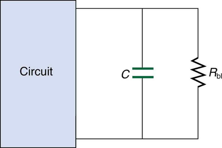
- An electronic apparatus may have large capacitors at high voltage in the power supply section, presenting a shock hazard even when the apparatus is switched off. A “bleeder resistor” is therefore placed across such a capacitor, as shown schematically in Figure 32.5, to bleed the charge from it after the apparatus is off. Why must the bleeder resistance be much greater than the effective resistance of the rest of the circuit? How does this affect the time constant for discharging the capacitor?
Problems & Exercises
- The timing device in an automobile’s intermittent wiper system is based on an [latex]\text{RC}[/latex] time constant and utilizes a [latex]0\text{.}\text{500-μF}[/latex] capacitor and a variable resistor. Over what range must [latex]R[/latex] be made to vary to achieve time constants from 2.00 to 15.0 s?
- A heart pacemaker fires 72 times a minute, each time a 25.0-nF capacitor is charged (by a battery in series with a resistor) to 0.632 of its full voltage. What is the value of the resistance?
- The duration of a photographic flash is related to an [latex]\text{RC}[/latex] time constant, which is [latex]0\text{.}\text{100 μs}[/latex] for a certain camera.
- If the resistance of the flash lamp is [latex]0\text{.}\text{0400}\,\Omega[/latex] during discharge, what is the size of the capacitor supplying its energy?
- What is the time constant for charging the capacitor, if the charging resistance is [latex]\text{800}\,\text{k}\Omega[/latex]?
- A 2.00- and a [latex]7\text{.}\text{50-μF}[/latex] capacitor can be connected in series or parallel, as can a 25.0- and a [latex]\text{100-k}\Omega[/latex] resistor. Calculate the four [latex]\text{RC}[/latex] time constants possible from connecting the resulting capacitance and resistance in series.
- After two time constants, what percentage of the final voltage (emf) is on an initially uncharged capacitor [latex]C[/latex], charged through a resistance [latex]R[/latex]?
- A [latex]\text{500-}\Omega[/latex] resistor, an uncharged [latex]1\text{.}\text{50-μF}[/latex] capacitor, and a 6.16-V emf are connected in series.
- What is the initial current?
- What is the [latex]\text{RC}[/latex] time constant?
- What is the current after one time constant?
- What is the voltage on the capacitor after one time constant?
- A heart defibrillator being used on a patient has an [latex]\text{RC}[/latex] time constant of 10.0 ms due to the resistance of the patient and the capacitance of the defibrillator.
- If the defibrillator has an [latex]8\text{.}\text{00-μF}[/latex] capacitance, what is the resistance of the path through the patient? (You may neglect the capacitance of the patient and the resistance of the defibrillator.)
- If the initial voltage is 12.0 kV, how long does it take to decline to [latex]6.00\times10^{2}\,\text{V}[/latex]?
- An ECG monitor must have an [latex]\text{RC}[/latex] time constant less than [latex]1.00\times10^{2}\,\text{μs}[/latex] to be able to measure variations in voltage over small time intervals.
- If the resistance of the circuit (due mostly to that of the patient’s chest) is [latex]1.00\,\text{k}\Omega[/latex], what is the maximum capacitance of the circuit?
- Would it be difficult in practice to limit the capacitance to less than the value found in (a)?
- Figure 32.6 shows how a bleeder resistor is used to discharge a capacitor after an electronic device is shut off, allowing a person to work on the electronics with less risk of shock.
- What is the time constant?
- How long will it take to reduce the voltage on the capacitor to 0.250% (5% of 5%) of its full value once discharge begins?
- If the capacitor is charged to a voltage [latex]V_0[/latex] through a [latex]\text{100-}\Omega[/latex] resistance, calculate the time it takes to rise to [latex]0.865V_0[/latex] (This is about two time constants.)
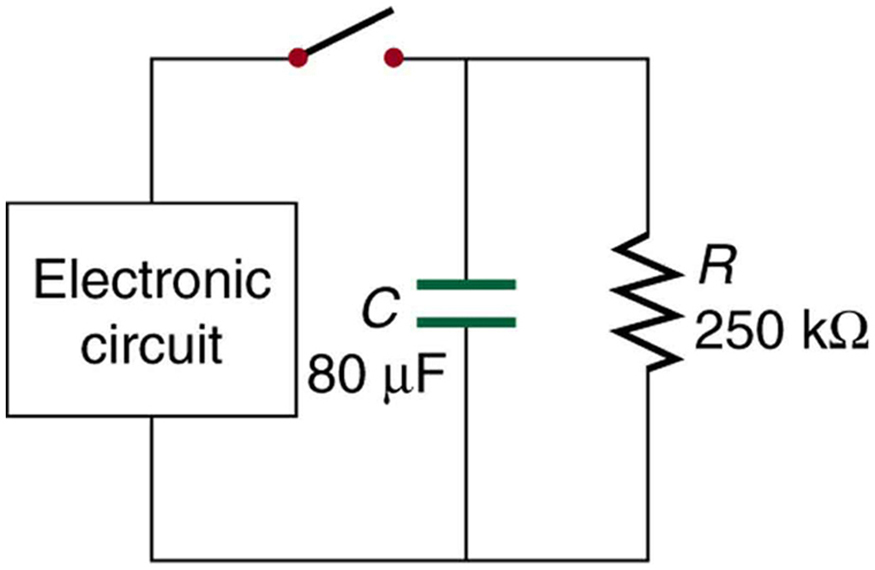
Figure 32.6: A bleeder resistor [latex]{R}_{\text{bl}}[/latex] discharges the capacitor in this electronic device once it is switched off. - Using the exact exponential treatment, find how much time is required to discharge a [latex]\text{250-μF}[/latex] capacitor through a [latex]\text{500-}\Omega[/latex] resistor down to 1.00% of its original voltage.
- Using the exact exponential treatment, find how much time is required to charge an initially uncharged 100-pF capacitor through a [latex]\text{75.0-M}\Omega[/latex] resistor to 90.0% of its final voltage.
- Integrated Concepts: If you wish to take a picture of a bullet traveling at 500 m/s, then a very brief flash of light produced by an [latex]\text{RC}[/latex] discharge through a flash tube can limit blurring. Assuming 1.00 mm of motion during one [latex]\text{RC}[/latex] constant is acceptable, and given that the flash is driven by a [latex]\text{600-μF}[/latex] capacitor, what is the resistance in the flash tube?
- Integrated Concepts: A flashing lamp in a Christmas earring is based on an [latex]\text{RC}[/latex] discharge of a capacitor through its resistance. The effective duration of the flash is 0.250 s, during which it produces an average 0.500 W from an average 3.00 V.
- What energy does it dissipate?
- How much charge moves through the lamp?
- Find the capacitance.
- What is the resistance of the lamp?
- Integrated Concepts: A [latex]\text{160-μF}[/latex] capacitor charged to 450 V is discharged through a [latex]31\text{.}2-\text{k}\Omega[/latex] resistor.
- Find the time constant.
- Calculate the temperature increase of the resistor, given that its mass is 2.50 g and its specific heat is [latex]1.67\frac{\text{kJ}}{\text{kg}\cdot\ ^\circ\ \text{C}}[/latex], noting that most of the thermal energy is retained in the short time of the discharge.
- Calculate the new resistance, assuming it is pure carbon.
- Does this change in resistance seem significant?
- Unreasonable Results:
- Calculate the capacitance needed to get an [latex]\text{RC}[/latex] time constant of [latex]1.00\times10^{3}\,\text{s}[/latex] with a [latex]0.100-\Omega[/latex] resistor.
- What is unreasonable about this result?
- Which assumptions are responsible?
- Construct Your Own Problem: Consider a camera’s flash unit. Construct a problem in which you calculate the size of the capacitor that stores energy for the flash lamp. Among the things to be considered are the voltage applied to the capacitor, the energy needed in the flash and the associated charge needed on the capacitor, the resistance of the flash lamp during discharge, and the desired [latex]\text{RC}[/latex] time constant.
- Construct Your Own Problem: Consider a rechargeable lithium cell that is to be used to power a camcorder. Construct a problem in which you calculate the internal resistance of the cell during normal operation. Also, calculate the minimum voltage output of a battery charger to be used to recharge your lithium cell. Among the things to be considered are the emf and useful terminal voltage of a lithium cell and the current it should be able to supply to a camcorder.
- Critical Thinking: A circuit has a voltage source producing [latex]1.00\times10^{2}\,\text{V}[/latex] and a [latex]2.50\times10^{3}\,\Omega[/latex] resistor.
- If the circuit contains nothing else, how much power is dissipated by the resistor?
- A second [latex]2.50\times10^{3}\,\Omega[/latex] resistor is added in parallel to the first resistor. Now how much power is dissipated by the resistors?
- Now place the two resistors in series. How much power is dissipated by the resistors?
- Why would a parallel arrangement of resistors dissipate more power than a series arrangement of resistors of the same value?
- Which delivers more energy in a given time period, the parallel combination of resistors, the series combination of resistors, or is the energy delivered in a given time period the same?
Glossary
- RC circuit
- A circuit that contains both a resistor (R) and a capacitor (C), producing characteristic charging and discharging behavior described by the RC time constant.
- capacitor
- An electrical component that stores electric charge and electrical energy by separating positive and negative charges on two conducting plates separated by an insulating material.
- capacitance
- A measure of a capacitor's ability to store electric charge. It is defined as the amount of charge stored per unit potential difference between the plates and is measured in farads (F).
- time constant
- The characteristic time of an RC circuit, given by [latex]\tau = RC[/latex]. After one time constant, a charging capacitor reaches about 63.2% of its final voltage, while a discharging capacitor falls to about 36.8% of its initial voltage.
The characteristic time of an RC circuit, given by [latex]\tau = RC[/latex]. After one time constant, a charging capacitor reaches about 63.2% of its final voltage, while a discharging capacitor falls to about 36.8% of its initial voltage.
A device that stores electrical energy by separating equal amounts of positive and negative charge on two conductors.
A circuit that contains both a resistor (R) and a capacitor (C), producing characteristic charging and discharging behavior described by the RC time constant.
The amount of electric charge stored per unit potential difference; mathematically, [latex]C=Q/V[/latex].
